Magnetic switch

a technology of magnetic switch and switch body, which is applied in the direction of electromagnetic relay details, contact fixed to the operating part, electrical apparatus, etc., can solve the problems of suppressing the intrinsic function of permanent magnets, increasing the number of components, and deteriorating the work process, so as to facilitate assembly and removal work, reduce the possibility of damaging the surrounding components, and simplify the effect of components

Active Publication Date: 2017-02-14
LSIS CO LTD
View PDF39 Cites 9 Cited by
  • Summary
  • Abstract
  • Description
  • Claims
  • Application Information

AI Technical Summary

Benefits of technology

[0014]The present invention is contrived to solve the foregoing problems, and an aspect of the present invention is to provide a magnetic switch provided with a permanent magnet disposed at an outside of an upper frame and an externally fitted permanent magnet holder so as to reduce a number of components and facilitate maintenance.
[0024]According to a magnetic switch according to an embodiment of the present disclosure, a permanent magnet may be coupled to an outside of the upper frame by a permanent magnet holder, thereby having an effect of facilitating the assembly and removal work. Furthermore, it may reduce possibility of damaging the surrounding components during the removal.
[0025]On the other hand, the permanent magnet holder may be configured with a single component, thereby implementing the simplification of components and reducing the manufacturing cost.

Problems solved by technology

In other words, there is a drawback of increasing the number of components and deteriorating the work process.
Furthermore, two permanent magnet holders 7 are pushed and installed into the upper frame 2, which is a plastic injection molded part, thereby causing a problem of suppressing the intrinsic function of permanent magnets 6a, 6b in case where the permanent magnet holders 7 are released therefrom.

Method used


Image

  • Magnetic switch
  • Magnetic switch
  • Magnetic switch

Examples


Embodiment Construction

[0036]Hereinafter, a preferred embodiment of the present invention will be described in detail with reference to the accompanying drawings to such an extent that the present invention can be easily implemented by a person having ordinary skill in the art to which the present invention pertains, but it does not mean that the technical concept and scope of the present invention are limited due to this.

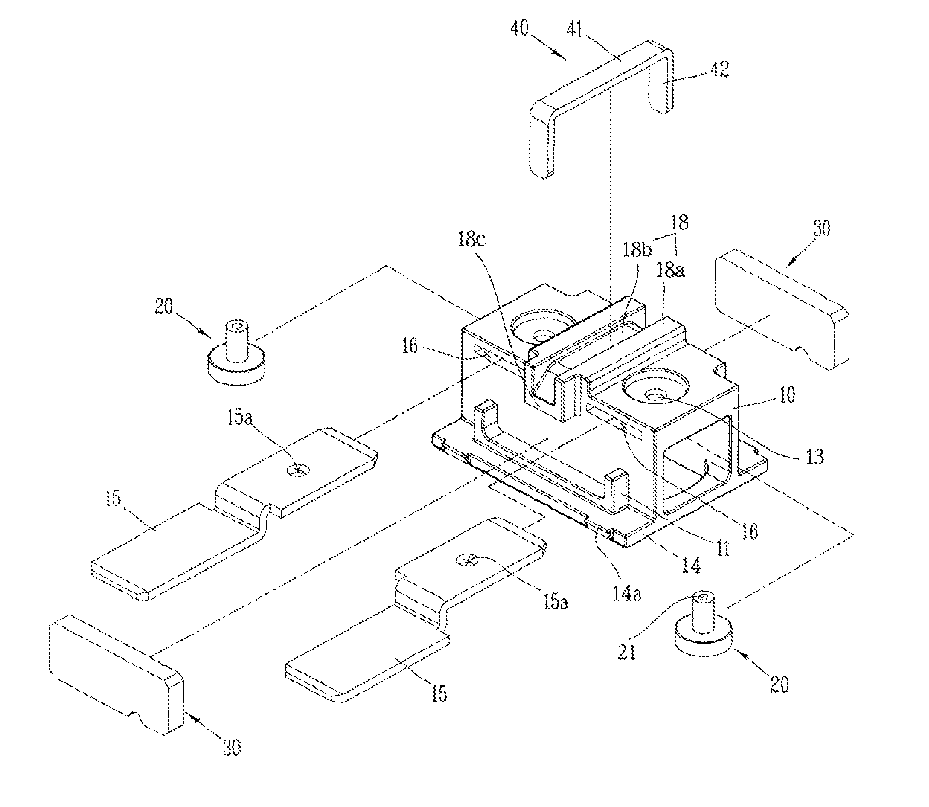
[0037]FIG. 4 illustrates a perspective view of a magnetic switch according to an embodiment of the present disclosure, and FIG. 5 illustrates an exploded perspective view of an upper frame assembly, and FIG. 6 illustrates a rear perspective view of an upper frame. A magnetic switch according to each embodiment of the present disclosure will be described in detail with reference to the accompanying drawings.

[0038]A magnetic switch according to an embodiment of the present disclosure may include an upper frame 10 formed in a box shape on which a lower surface thereof is open; a pair of fix...


PUM


Abstract

The present invention relates to a magnetic switch, and more particularly, to a magnetic switch provided with a permanent magnet disposed at an outside of an upper frame and an externally fitted permanent magnet holder to reduce a number of components and facilitate maintenance.

Description

CROSS-REFERENCE TO RELATED APPLICATIONS[0001]Pursuant to 35 U.S.C. §119(a), this application claims the benefit of earlier filing date and right of priority to Korean Patent Application No. 10-2015-0051883, filed on Apr. 13, 2015, the contents of which are hereby incorporated by reference herein in its entirety.BACKGROUND OF THE INVENTION[0002]1. Field of the Invention[0003]The present invention relates to a magnetic switch, and more particularly, to a magnetic switch provided with a permanent magnet disposed at an outside of an upper frame and an externally fitted permanent magnet holder to reduce a number of components and facilitate maintenance.[0004]2. Description of the Related Art[0005]In general, as a type of electrical circuit switching device for transferring mechanical drives and current signals using the principle of an electromagnet, a magnetic switch or direct current relay is installed in various facilities, machines, vehicles and the like.[0006]In particular, in case ...

Claims


Application Information

Patent Timeline
Patent Type & Authority Patents(United States)
IPC IPC(8): H01H67/02H01H50/16H01H50/04H01H9/44H01H50/44H01H1/20
CPCH01H50/16H01H9/443H01H50/041H01H50/44H01H1/20H01H2050/046H01H2205/002H01H50/042
Inventor PARK, JINHEE
Owner LSIS CO LTD
Why Eureka
Try Eureka