Radar antenna and radar antenna manufacturing method

a technology of radar antenna and manufacturing method, which is applied in the direction of antennas, instruments, electrical equipment, etc., can solve the problems of increased manufacturing cost of radar antennas, inability to form beams appropriately, and exposed outside of coaxial cable or the like connecting the antenna unit with the housing unit, etc., and achieves the effect of simple configuration

Active Publication Date: 2017-02-14
FURUNO ELECTRIC CO LTD
View PDF8 Cites 0 Cited by
  • Summary
  • Abstract
  • Description
  • Claims
  • Application Information

AI Technical Summary

Benefits of technology

[0011]The present invention is made in view of the above situations, and mainly aims to provide a radar antenna that protects a coaxial cable connecting an antenna unit with a housing unit, with a simple configuration.

Problems solved by technology

However, with the antenna unit having the dielectric bodies as disclosed in JP1991-042723A, when a metal is disposed near the antenna unit, a beam cannot be formed appropriately.
However, in this case, it is concerned that a coaxial cable or the like connecting the antenna unit with the housing unit will be exposed outside.
As a result, the manufacturing cost of the radar antennas increases.
Moreover, in the case where the coaxial cable is exposed outside, the appearance of the radar antenna will seem untidy and it is not preferable also in view of the design.

Method used


Image

  • Radar antenna and radar antenna manufacturing method
  • Radar antenna and radar antenna manufacturing method
  • Radar antenna and radar antenna manufacturing method

Examples


Embodiment Construction

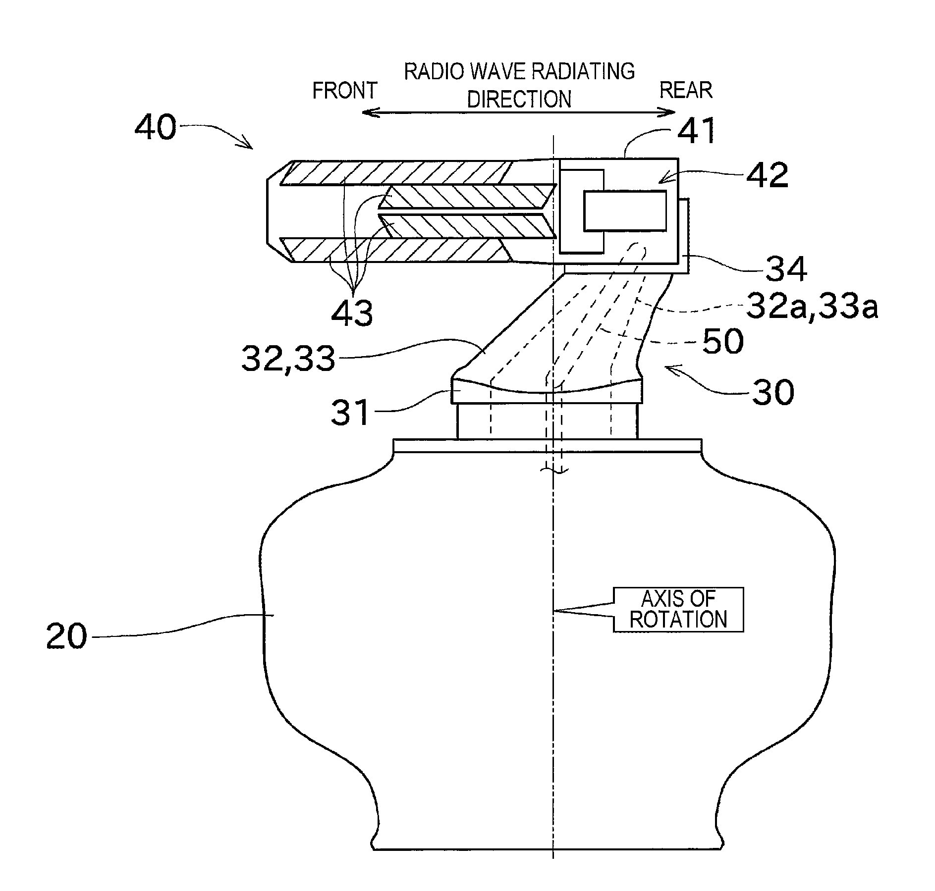
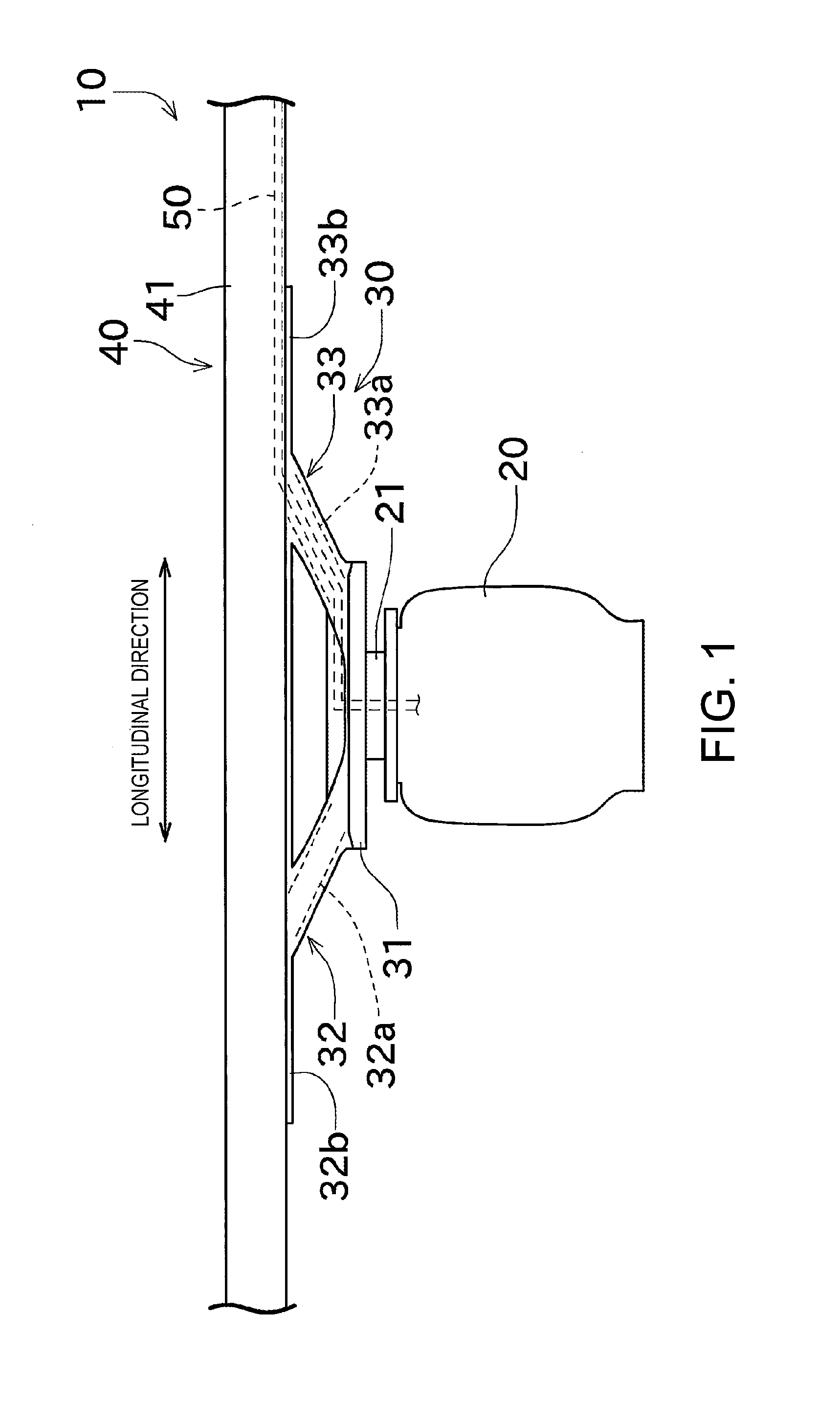
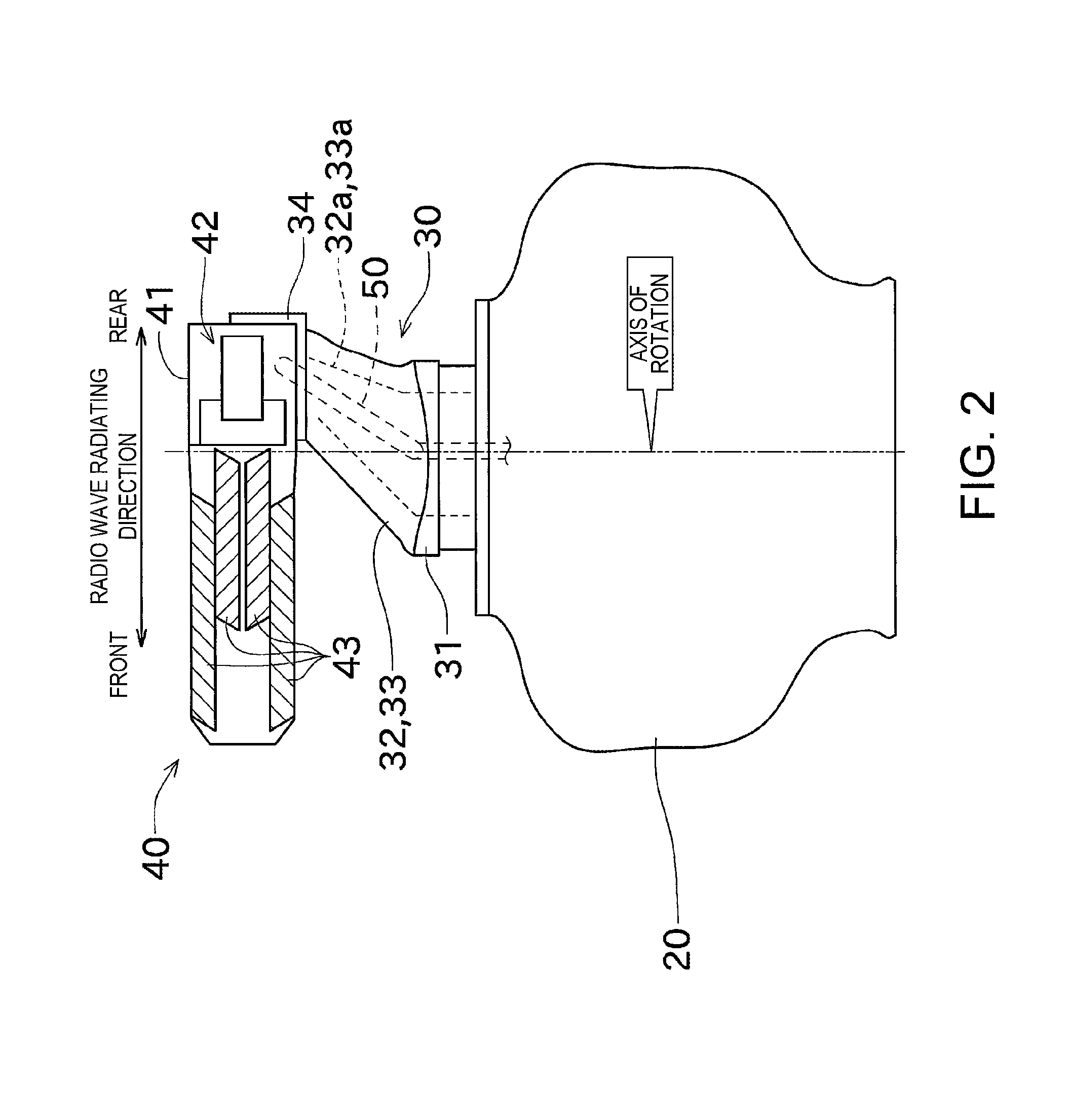
[0033]Next, one embodiment of the present invention is described with reference to the accompanying drawings. FIG. 1 is a schematic front view of a radar antenna according to this embodiment of the present invention. FIG. 2 is a schematic side view of the radar antenna.

[0034]A radar antenna 10 radiates pulse-shaped radio waves and receives reflection waves of the radiated radio waves. The radar antenna 10 repeats transception of the radio waves while rotating in the horizontal plane. Each reflection wave received by the radar antenna 10 is analyzed by a transceiver, an indicator and the like (not illustrated). Thus, a position, a speed and the like of a target object existing around the radar antenna 10 can be obtained.

[0035]As illustrated in FIGS. 1 and 2, the radar antenna 10 includes a housing unit 20, an antenna supporting unit 30, and an antenna unit 40 having dielectric bodies.

[0036]The housing unit 20 is a box-like member accommodating various components. The housing unit 20 ...


PUM

PropertyMeasurementUnit
transmission frequencyaaaaaaaaaa
dielectricaaaaaaaaaa
shapeaaaaaaaaaa

Abstract

A radar antenna is provided. The radar antenna includes an antenna unit provided with dielectric bodies in a front part thereof in a radio wave radiating direction, a pedestal, a supporting bar attached between the antenna unit and the pedestal to separate the antenna unit from the pedestal, and formed with a hollow section therein, and one of a cable and a waveguide passing through the hollow section and connected with the antenna unit.

Description

CROSS-REFERENCE TO RELATED APPLICATION(S)[0001]This application claims priority under 35 U.S.C. §119 to Japanese Patent Application No. 2012-258704, which was filed on Nov. 27, 2012, the entire disclosure of which is hereby incorporated by reference.TECHNICAL FIELD[0002]The present invention relates to a radar antenna including an antenna unit having dielectric bodies.BACKGROUND OF THE INVENTION[0003]Conventionally, radar antennas each including an antenna unit and a housing unit has been known. The antenna unit radiates outside radio waves. The housing unit is built therein with a motor for rotating the antenna unit, a coaxial cable for supplying radio waves to the antenna unit, etc.[0004]Moreover, various kinds of antenna units have conventionally been known, such as, an antenna unit having a shape in which the cross-section of an opening part thereof becomes gradually spreads wider toward outside (horn shape, trumpet shape). In supporting the horn-shaped antenna unit, it has been...

Claims


Application Information

Patent Timeline
Patent Type & Authority Patents(United States)
IPC IPC(8): H01Q1/12H01Q3/04
CPCH01Q3/04Y10T29/49016G01S7/03H01Q1/12
Inventor MIYAGAWA, TETSUYAATSUMI, KOJIFURUGORI, KAZUYOSHIODA, MAKOTO
Owner FURUNO ELECTRIC CO LTD
Why Eureka
Try Eureka