Vacuum drilling system and methods

a vacuum drilling and vacuum technology, applied in the field of vacuum drilling, can solve the problems of releasing chips and coolant into the environment, compact portable drilling machines, and large components, and achieve the effects of maximizing the precision of drilling operation, promoting heat dissipation and chip removal, and efficient extraction of chips

Active Publication Date: 2017-02-21
ALLIED MASCH & ENG CORP
View PDF58 Cites 4 Cited by
  • Summary
  • Abstract
  • Description
  • Claims
  • Application Information

AI Technical Summary

Benefits of technology

[0009]The present invention provides a vacuum drilling system for a drilling operation that utilizes both a through tool coolant supply as well as a central vacuum extraction system. In an example, the drilling system includes a generally cylindrical body member and a cutting head at the front end of the body member having at least one cutting edge formed thereon. The body member forms a hollow shaft adjacent the cutting head with at least one opening formed in the body member adjacent the cutting head. A coolant adapter provided on the body member provides a coolant fluid through at least one sealed channel in the body member exterior to the hollow shaft, to provide the coolant fluid to the area of the at least one cutting edge. A vacuum connected to the hollow shaft applies vacuum pressure through the at least one opening and hollow shaft. The through tool coolant system is provided by a sealed coolant containment channels situated around a hollow interior channel that remains unrestricted and is sized to efficiently extract chips formed during a drilling operation. The invention can be used in drilling operations wherein chips formed during drilling are vacuum extracted and coolant is supplied to promote heat dissipation and chip removal and maximize the precision of the drilling operation while increasing tool life.
[0010]The present invention also provides a method of performing a drilling operation comprising providing a drilling tool having a cutting head adjacent a front end of the drilling tool having at least one cutting edge formed thereon. The drilling tool also includes a hollow shaft with at least one opening formed adjacent the cutting head. A coolant adapter is provided on the body member to provide a coolant fluid through at least one sealed channel in the body member exterior to the hollow shaft. A vacuum source is coupled to the hollow tube to extract cuttings formed at the cutting head. The through tool coolant system is provided by at least one sealed coolant containment channel situated around a hollow interior channel that remains unrestricted and is sized to efficiently extract chips formed during a drilling operation.

Problems solved by technology

For example, in the aerospace industry, the components may be very large and require portable drilling machines that can be moved to the different hole locations on the component.
The portable drilling machines are compact and do not provide any enclosure to isolate the drilling process from the outside environment.
This results in the release of chips and coolant into the environment when utilizing solid twist drills.
Additionally, failure to contain the chips and coolant flow may cause health and safety hazards for drill operators.
Additionally, the generation of chips during the drilling of various materials requires the chips to be conveyed away from the cutting features of the drill, or the chips can impede the drilling process and / or cause damage to the drill.
Without effective removal of the chips thus generated, chip compaction often occurs, reducing the drill's ability to cut, increasing the generation of heat, and reducing the life of the drill.
For example, in materials such as titanium and aluminum, it would be desirable to facilitate removal of chips using an applied vacuum, but with metallic materials, the prior vacuum systems for CFRP materials are not designed to be used on such materials.

Method used


Image

  • Vacuum drilling system and methods
  • Vacuum drilling system and methods
  • Vacuum drilling system and methods

Examples


Embodiment Construction

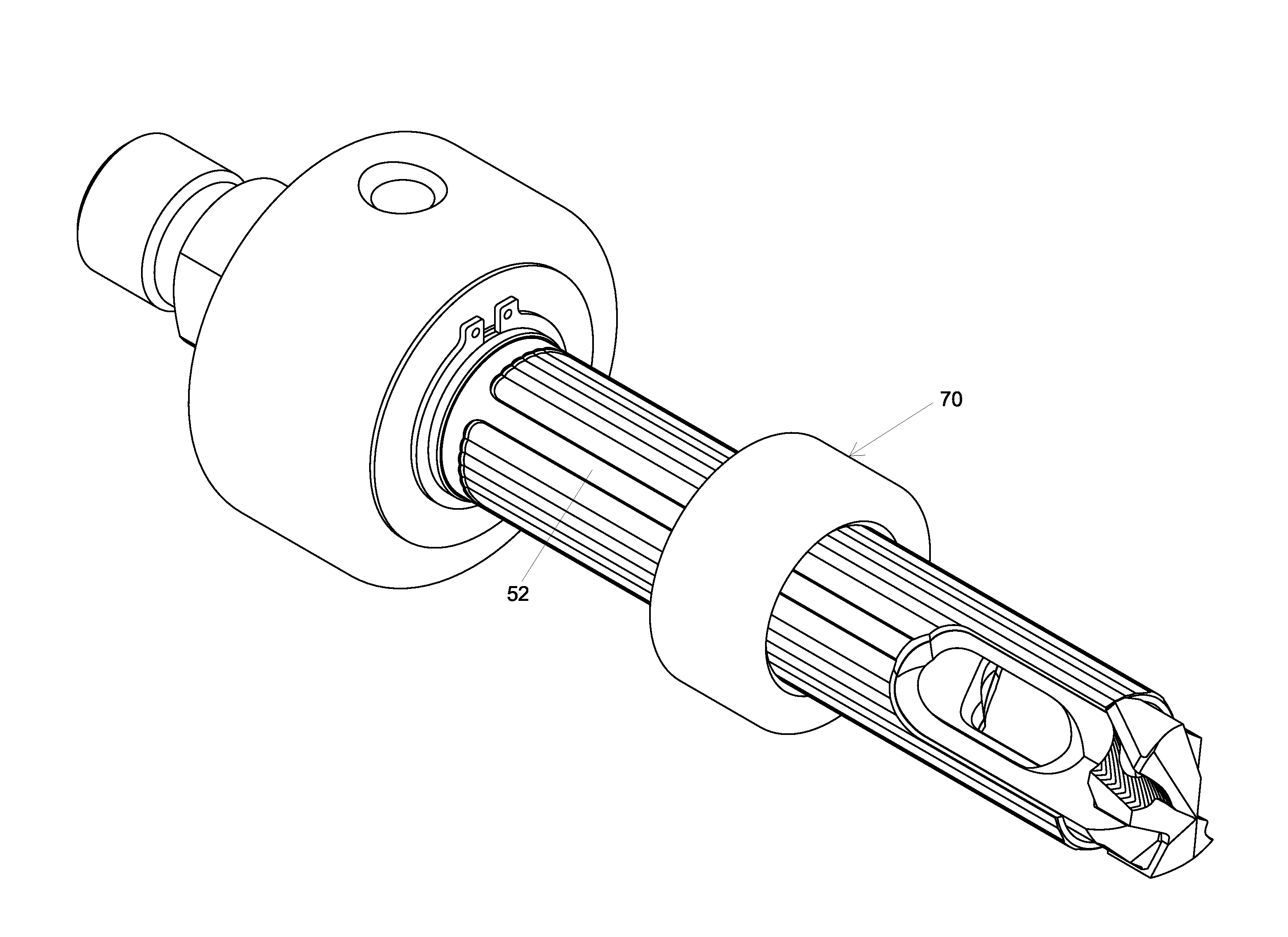
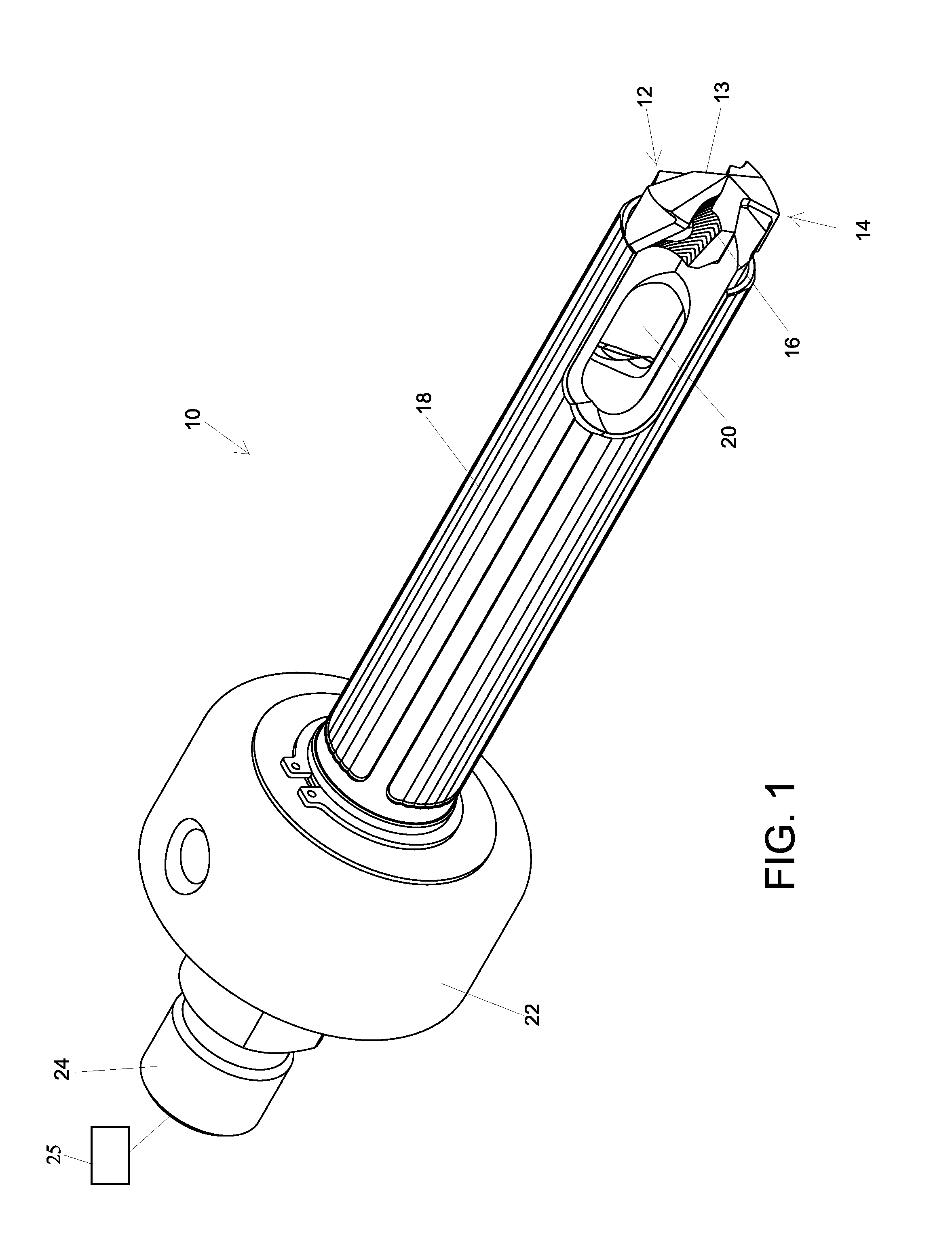
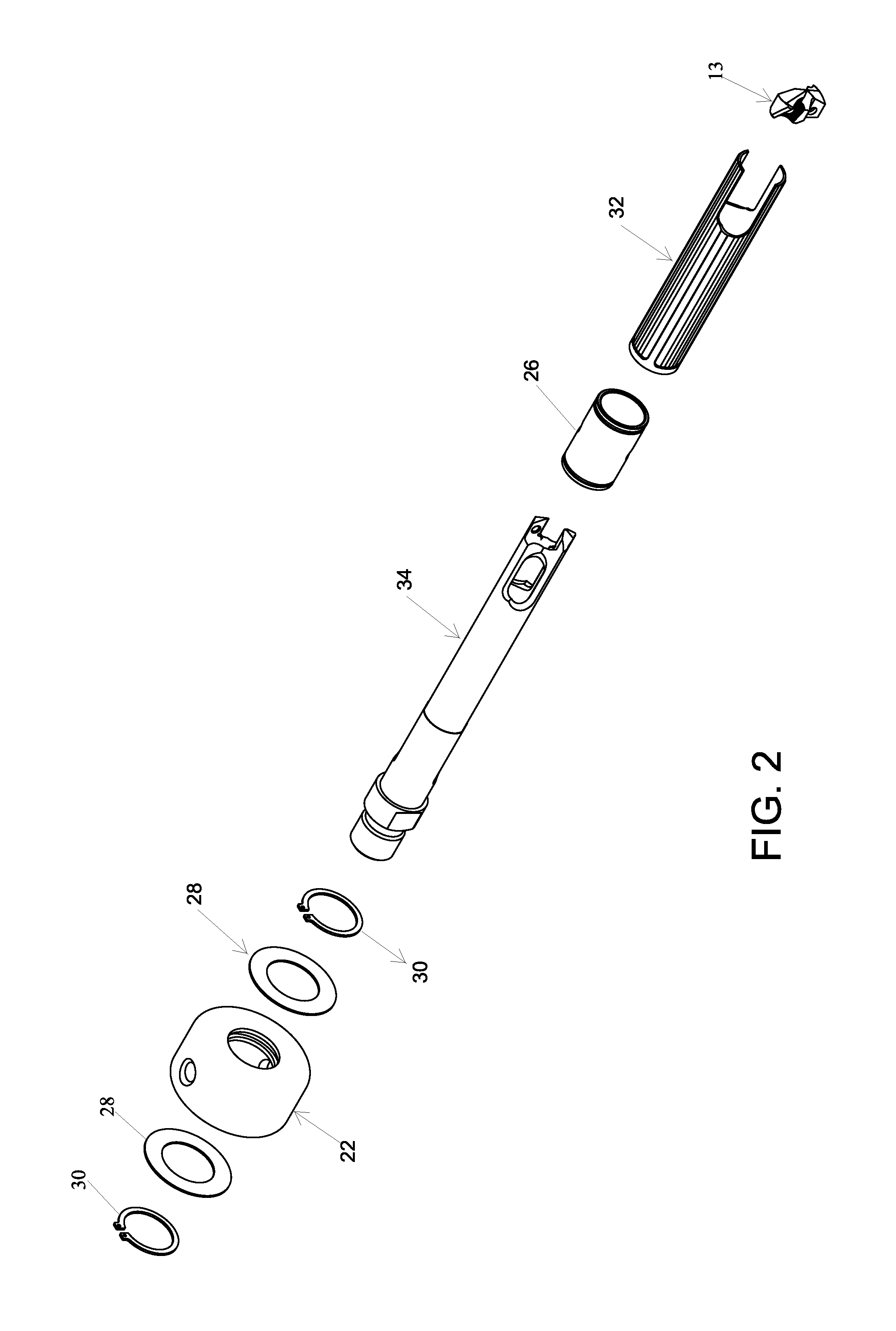
[0019]An example of a vacuum drilling system 10 in accordance with the present invention is shown in FIGS. 1 and 2. The vacuum drilling system 10 for performing a drilling operation may include a variety of features and attributes to promote heat dissipation and chip removal, and maximize the precision of the drilling operation while increasing tool life. The vacuum drilling system 10 utilizes both a through tool coolant supply as well as a central vacuum extraction system. In this example, the system may include a cutting head 12 adjacent a front end 14 of the system, having at least one cutting edge 16 formed thereon. A hollow shaft 18 is provided with at least one front hole or opening 20 adjacent the cutting head 12. A rotary coolant adapter 22 is provided on the shaft 18 adjacent at least one rear opening 24. A vacuum source 25 is connected to apply vacuum pressure in the formed hole as will be described hereafter. Vacuum pressure is applied through the openings 20 and hollow s...


PUM

PropertyMeasurementUnit
diameteraaaaaaaaaa
vacuum pressureaaaaaaaaaa
outer diameteraaaaaaaaaa

Abstract

A vacuum drilling system and methods is provided that may utilize both a through tool coolant supply as well as a central vacuum extraction system. The system may include a cutting head provided on a hollow tube and a vacuum source to apply vacuum pressure to the area of the cutting head via one or more chip inlets arranged proximate to the cutting head. Sealed coolant containment channels supply coolant to the area of the cutting head.

Description

CROSS-REFERENCE TO RELATED APPLICATION[0001]This U.S. patent application claims the benefit of and priority to U.S. Provisional Patent Application Ser. No. 61 / 828,056, filed May 28, 2013, which is incorporated herein by reference in its entirety.FIELD OF THE INVENTION[0002]The present invention relates to the field of drilling, and in particular, to vacuum drilling systems, which provide for the collection of chips generated by the drilling process by an applied vacuum, while also allowing for through tool coolant application.BACKGROUND INFORMATION[0003]In various industries and applications, drilling of materials may be performed using solid twist drill designs. In the aerospace industry for example, to successfully drill the various metals used in the industry, solid twist drills provide desired capabilities, such as being precise. This style of tooling may have through coolant capability and the coolant outlets typically exit on the clearance angle of the cutting geometry at the ...

Claims


Application Information

Patent Timeline
Patent Type & Authority Patents(United States)
IPC IPC(8): B23B51/06
CPCB23B51/06B23B2251/50B23B2251/68Y10T408/03Y10T408/04Y10T408/453B23B2260/072
Inventor BEST, PAUL W.POLILLI, RICHARD D.CARLISLE, DAVID J.
Owner ALLIED MASCH & ENG CORP
Why Eureka
Try Eureka