Method for automated position detection by defining an evaluation region of a register sensor

a technology of register sensor and evaluation region, which is applied in the direction of pile separation, instruments, transportation and packaging, etc., can solve the problems of waste sheet production, and achieve the effect of avoiding adjustment errors

Active Publication Date: 2017-02-21
HEIDELBERGER DRUCKMASCHINEN AG
View PDF7 Cites 1 Cited by
  • Summary
  • Abstract
  • Description
  • Claims
  • Application Information

AI Technical Summary

Benefits of technology

[0004]It is accordingly an object of the invention to provide a method for automated position detection by defining an evaluation region of a register sensor for detecting register marks on printing substrates in printing substrate processing machines, which overcomes the hereinafore-mentioned disadvantages of the heretofore-known methods of this general type and which avoids adjustment errors caused by an operator.
[0007]In accordance with a first embodiment of the invention, a provision is made for a value of the evaluation region to be saved in the computer as a final value upon the detection of an edge of the register mark on the printing substrate, thus effectively saving the evaluation region. As soon as the register sensor detects the first edge of the register mark on the printing substrate, the evaluation region reaches its final size, which means that the value of the evaluation region is defined and may automatically be saved in the computer of the machine. In this way, the evaluation region is defined in an automated way and there is no risk for the operator to define a wrong evaluation region, in particular an evaluation region that is too wide and includes the opposite edge of the register mark, thus potentially causing errors in particular due to “jumping” to the wrong register mark edge.
[0009]In accordance with a further embodiment of the invention, an additional provision is made for the evaluation region to be widened by a sidelay error of the machine for processing printing substrates. The widening of the evaluation region by a sidelay error of the machine for processing printing substrates ensures that at least the first edge of the register mark is detected even if the maximum acceptable sidelay error occurs in the machine for processing printing substrates. An important aspect in this context is to make sure that the value of the sidelay error to be taken into consideration is smaller than half the distance between the two edges of the register mark. This is the only way to ensure that even when the maximum sidelay error occurs in the machine, only precisely one edge, namely the first register mark edge located on the side of the sheet edge, is located within the evaluation region. This is a reliable way to prevent “jumping” between the two edges of the register mark.
[0012]The target distance between the register mark and the edge of the printing substrate may easily be obtained from the pre-press data and may be read into the computer. In theory, this distance ought to be identical with the defined evaluation region that extends precisely up to the first outer edge of the register mark. When deviations that exceed acceptable tolerances are detected in this comparison, it is to be assumed that the detection of the edge of the register mark has been incorrect and that potentially a different edge, for instance a varnish edge, has erroneously been detected. Thus a comparison with pre-press data acts as a plausibility check and assists in preventing an erroneous detection of an edge of the register mark.

Problems solved by technology

This process of gradually approaching the first edge of the register mark ensures that the evaluation region will never be big enough to detect more than one edge of the register mark, for if the evaluation region was to include the opposite edge of the register mark, too, there would be the risk of the wrong edge of the register mark being taken as the reference value, causing the positioning of the printing substrate to be offset by the width of the register mark and consequently resulting in the production of waste sheets—a phenomenon that may also be referred to as “jumping.”
In this way, the evaluation region is defined in an automated way and there is no risk for the operator to define a wrong evaluation region, in particular an evaluation region that is too wide and includes the opposite edge of the register mark, thus potentially causing errors in particular due to “jumping” to the wrong register mark edge.

Method used


Image

  • Method for automated position detection by defining an evaluation region of a register sensor
  • Method for automated position detection by defining an evaluation region of a register sensor

Examples


Embodiment Construction

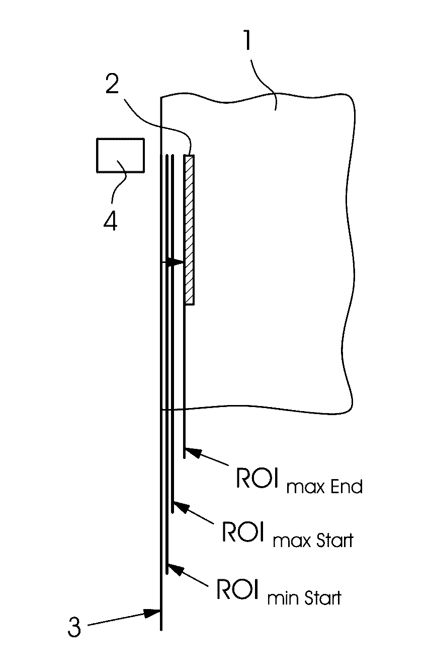
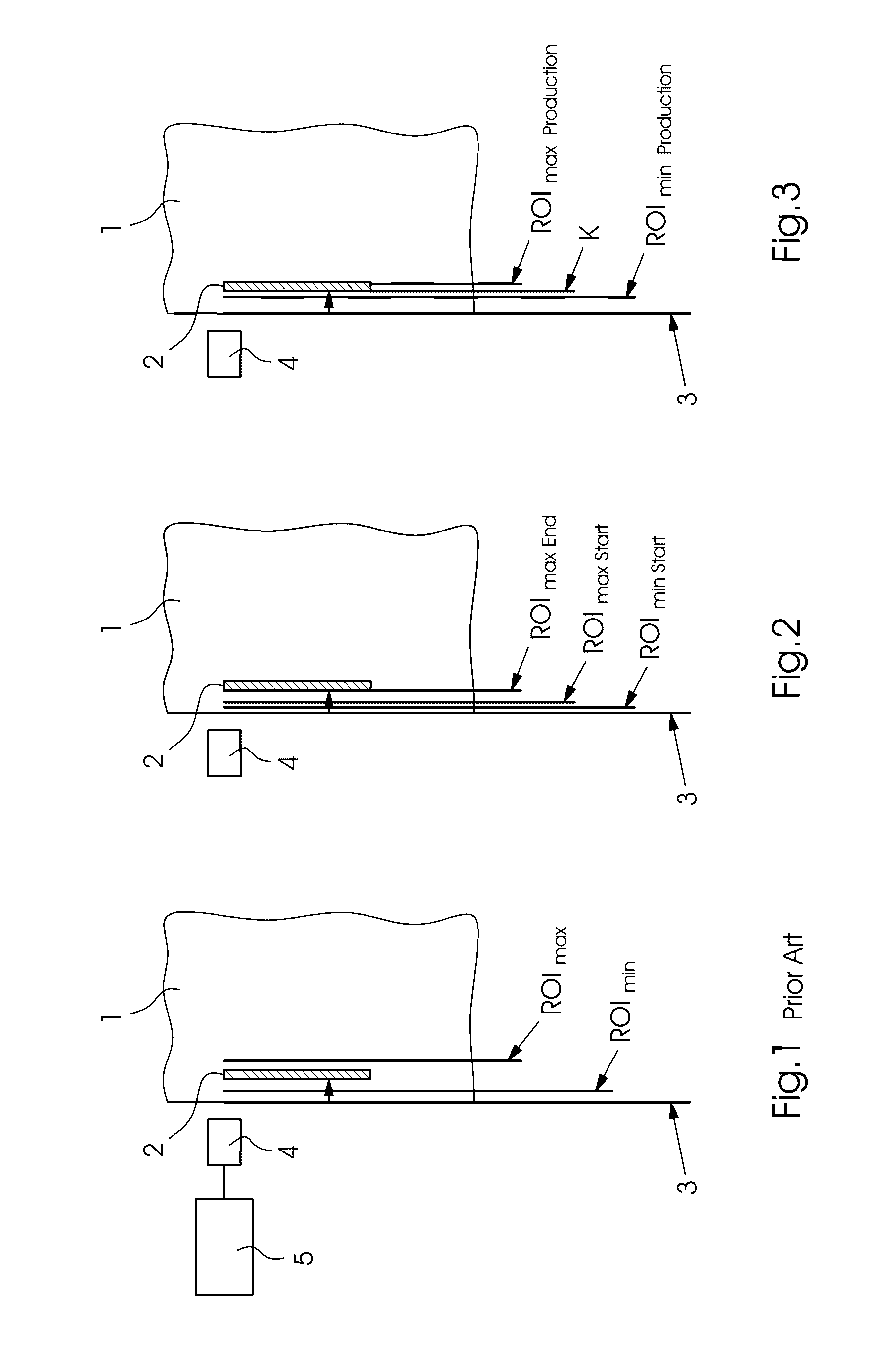
[0021]Referring now to the figures of the drawings in detail and first, particularly, to FIG. 1 thereof, there is seen a sheet-shaped printing substrate 1 onto which a register mark 2 has been printed. The register mark 2 has a specific width and is laterally bordered by two edges that are generally parallel to the edge of the sheet 1. A register sensor 4 is provided to detect the sheet edge 3 and the register mark 2. The register sensor 4 is connected to a control unit 5 of the machine for processing printing substrates. In accordance with the prior art, in order to define an evaluation region ROI, the evaluation region ROI is adjusted directly from a minimum ROI value ROImin to a maximum ROI value ROImax. However, a risk inherent in that process is that both edges of the register mark 2 may be located in the evaluation region ROI, causing two edges of the register mark 2 to be detected. If the wrong edge of the register mark 2 is taken as a reference for the alignment of the sheet...


PUM


Abstract

A method for defining an evaluation region of a register sensor for detecting register marks on printing substrates in printing substrate processing machines includes connecting the register sensor to a computer. In a first step, the register sensor measures an edge of a printing substrate, starting from the edge, the evaluation region is set to a starting value, and in at least one second step, the evaluation region is set to an increased value until the register sensor detects a first edge of the register mark.

Description

CROSS-REFERENCE TO RELATED APPLICATION[0001]This application claims the priority, under 35 U.S.C. §119, of German Application DE 10 2015 203 669.3, filed Mar. 2, 2015; the prior application is herewith incorporated by reference in its entirety.BACKGROUND OF THE INVENTIONField of the Invention[0002]The present invention relates to a method for automated position detection by defining an evaluation region of a register sensor for detecting register marks on printing substrates in printing substrate processing machines wherein the register sensor is connected to a computer.[0003]Register sensors of this type for detecting sheet edges or register marks on printing substrates are in particular used in printing presses and sheet-fed die-cutting machines to control the positioning of the sheet-shaped printing substrates as they are fed to the machine, for instance. In most cases, optical sensors are used in this process. In order to be able to adjust the feeding and positioning of the prin...

Claims


Application Information

Patent Timeline
Patent Type & Authority Patents(United States)
IPC IPC(8): B65H9/20G01B11/24B41F33/00B41F33/14
CPCB65H9/20B41F33/0081B41F33/14G01B11/24B65H2553/40B41P2233/52B65H2511/413B65H2511/5125B65H2553/41B65H2553/42G06F3/1208G06F3/125G06F3/1293B65H2511/512
Inventor FEISTAUER, HARALDHEITMANN, EIKELEONHARDT, HOLGER
Owner HEIDELBERGER DRUCKMASCHINEN AG
Why Eureka
Try Eureka