Phase-shift digital holographic high-speed imaging method and system

A high-speed imaging and digital holography technology, applied in the field of holography, can solve the problems of complex process, large error in reproduction results, inability to apply high-speed recording, etc., and achieve the effect of avoiding environmental changes and eliminating zero-order and conjugate images.

Inactive Publication Date: 2015-07-01
SHENZHEN UNIV
View PDF4 Cites 0 Cited by
  • Summary
  • Abstract
  • Description
  • Claims
  • Application Information

AI Technical Summary

Problems solved by technology

However, most of this method uses piezoelectric ceramics, rotating wave plates, etc. to achieve phase shift results, and requires multiple recordings of holograms with different phase shifts, so it cannot be applied to high-speed recording processes
In order to use the phase shift method to record the high-speed process, Japanese scholar Yasuhiro Awatsuji et al. proposed the method of parallel phase shift, which can record the high-speed process, but it needs to make an accurate mask, the process is complicated, and it can only record objects with a relatively uniform surface. For objects with large fluctuations, the error of the reproduction result is large

Method used


Image

  • Phase-shift digital holographic high-speed imaging method and system
  • Phase-shift digital holographic high-speed imaging method and system
  • Phase-shift digital holographic high-speed imaging method and system

Examples


Embodiment 2

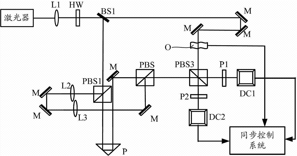
[0078] Example two such as figure 2 shown, with figure 1 In comparison, the second non-polarizing beam splitter BS2 is reduced and directly enters the third polarizing beam splitter PBS3, which is used to split the zero-phase-shifted reference light and the π-phase-shifted reference light, and respectively combine them with the object light of the corresponding polarization state Interference is carried out, and the first polarizer P1 and the second polarizer P2 are respectively added in front of the two digital cameras to output two holograms, wherein the first polarizer P1 is located at the output of the transmitted light of the third polarizing beam splitter PBS3 side for outputting the first hologram; the second polarizer P2 is located on the light exit side of the reflected light of the third polarizing beam splitter PBS3 and is used for outputting the second hologram.

Embodiment 1

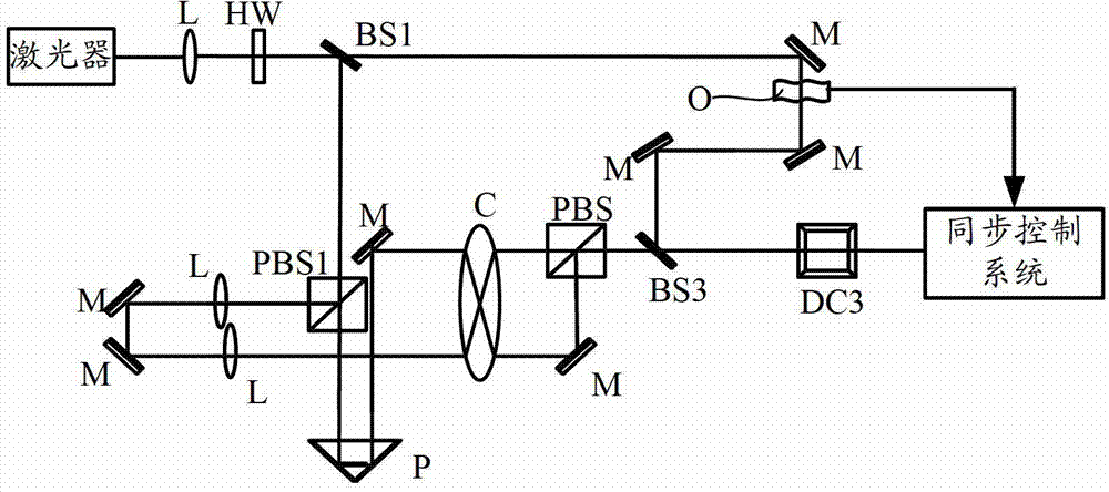
[0079]Embodiment 1 and Embodiment 2 both use two digital cameras to record. This method needs to strictly align the two digital cameras to ensure the spatial correspondence of the two holograms, which increases the difficulty for practical operation. In order to solve this problem, Embodiment 3 adopts adding a chopper to the two reference beams, such as image 3 As shown, the optical chopper C is located at the light exit side of the zero-phase-shift reference light generation component and the light-exit side of the π-phase-shift reference light generation component at the same time, and is used for the zero-phase-shift reference light and the π-phase The zero-phase-shifted reference light and the π-phase-shifted reference light are output alternately. The optical chopper C can modulate the continuous light into a periodic intermittent light with a certain frequency, control the rotation frequency of the optical chopper C so that the two beams of reference light with zero pha...


PUM


Abstract

The invention is applicable to the technical field of hologram photography and provides a phase-shift digital holographic high-speed imaging method which comprises the following steps: step A, using a light source to irradiate a target object to produce an object light carrying object information; step B, interfering the object light respectively with a zero phase-shift reference light and a pi phase-shift reference light, forming two holograms each time; step C, recovering an original light field of the target object according to the two holograms. The method provided by the invention can obtain two reference lights of zero phase shift and pi phase shift by one time through producing pi phase shift in one reference light with respect to the other reference light, avoid repeated phase shift and environmental change such as vibration and regulation error caused by the repeated phase shift, recover the original object light field by a simple algorithm according to the two holograms, effectively removing zero-order and conjugate images, and provide a feasible method for real-time recording in a high-velocity motion process.

Description

technical field [0001] The invention belongs to the technical field of holography, and in particular relates to a phase-shift digital holographic high-speed imaging method and system. Background technique [0002] Holography has been used in many aspects since it was proposed, such as three-dimensional imaging, shape measurement, etc., but traditional optical holography requires chemical wet processing, the process is complicated, and it is difficult to digitize, while digital holography uses digital cameras instead of photosensitive records. The medium can directly obtain the data, and the analysis is convenient and simple, so it has aroused the interest of many scholars. However, due to the limitation of large pixel size and small number of pixels in current digital cameras, off-axis holograms with small angles can only be recorded, and high spatial frequency information cannot be recorded. Coaxial holography can make full use of the space-bandwidth product of the camera,...

Claims


Application Information

Patent Timeline
Patent Type & Authority Patents(China)
IPC IPC(8): G03H1/22G03H1/12
Inventor 陆小微徐世祥李景镇
Owner SHENZHEN UNIV
Why Eureka
Try Eureka