Drill chuck assembly

a technology of drill chuck and assembly, which is applied in the direction of chucks, mechanical equipment, manufacturing tools, etc., can solve the problems of slowing a user's work, and affecting the work efficiency of users

Inactive Publication Date: 2017-02-28
HOMOLA KAARLE
View PDF15 Cites 0 Cited by
  • Summary
  • Abstract
  • Description
  • Claims
  • Application Information

AI Technical Summary

Problems solved by technology

However, there are many jawed chucks of the keyless variety, which involve the tightening and loosening of tools therein by hand force alone.
When employing the majority of these chucks, however, it is often difficult for a user to quickly change a drill bit for another.
For instance, the majority of chucks can neither accept different drill bits, which then requires the changing of the chuck altogether if a different drill bit is required, nor have releasing mechanisms that enable a user to change the drill bit without having to manipulate the chuck with their hands.
Furthermore, there are instances when a chuck's releasing mechanism is not directly accessible by a user, thereby requiring the user to manipulate the tool more than necessary.
These are setbacks that slows a user's work and makes it awkward for him or her to quickly exchange one drill bit shank for another.

Method used


Image

  • Drill chuck assembly
  • Drill chuck assembly
  • Drill chuck assembly

Examples


Embodiment Construction

[0016]Reference is made herein to the attached drawings. Like reference numerals are used throughout the drawings to depict like or similar elements of the drill chuck assembly. The figures are intended for representative purposes only and should not be considered to be limiting in any respect.

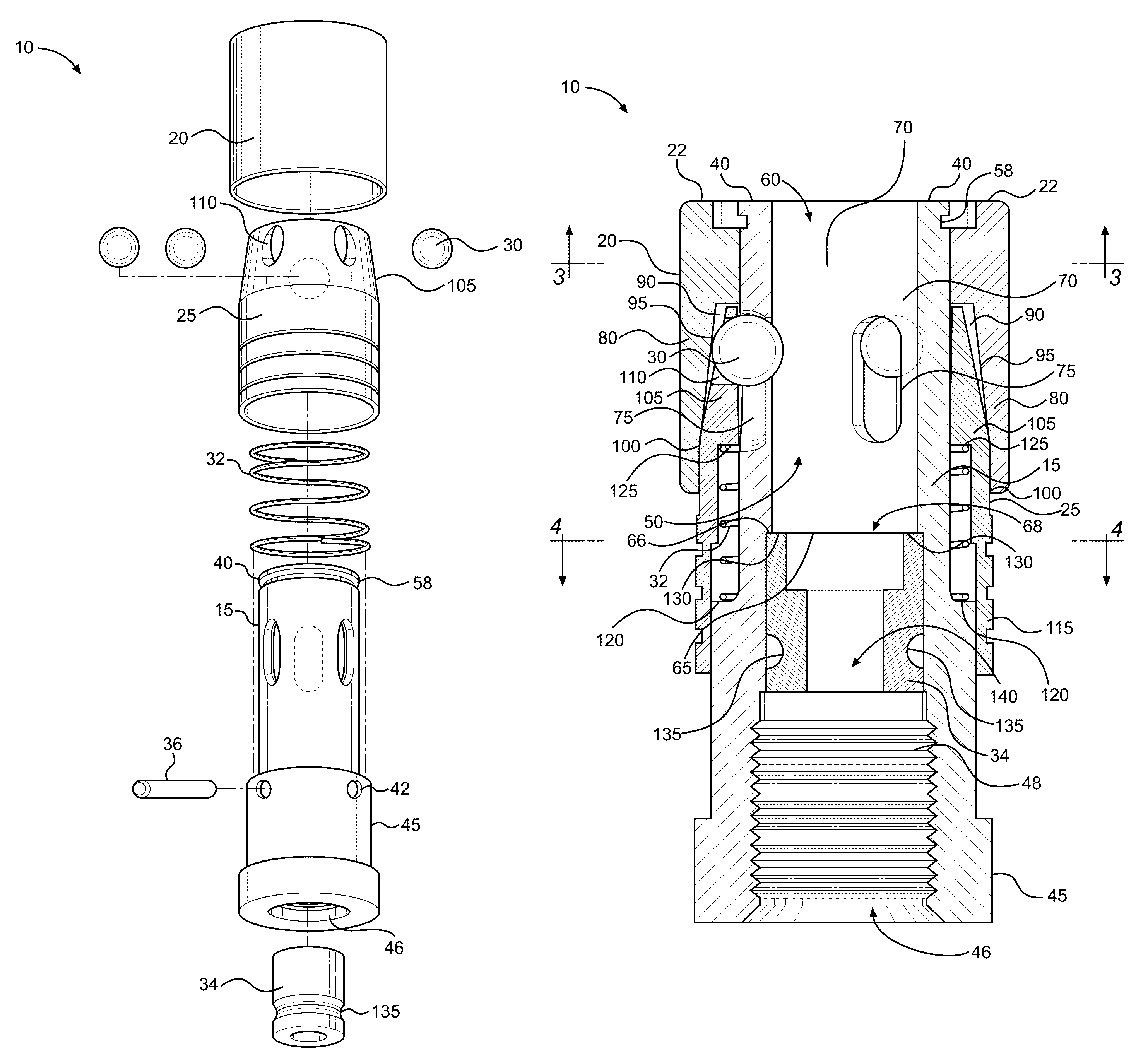
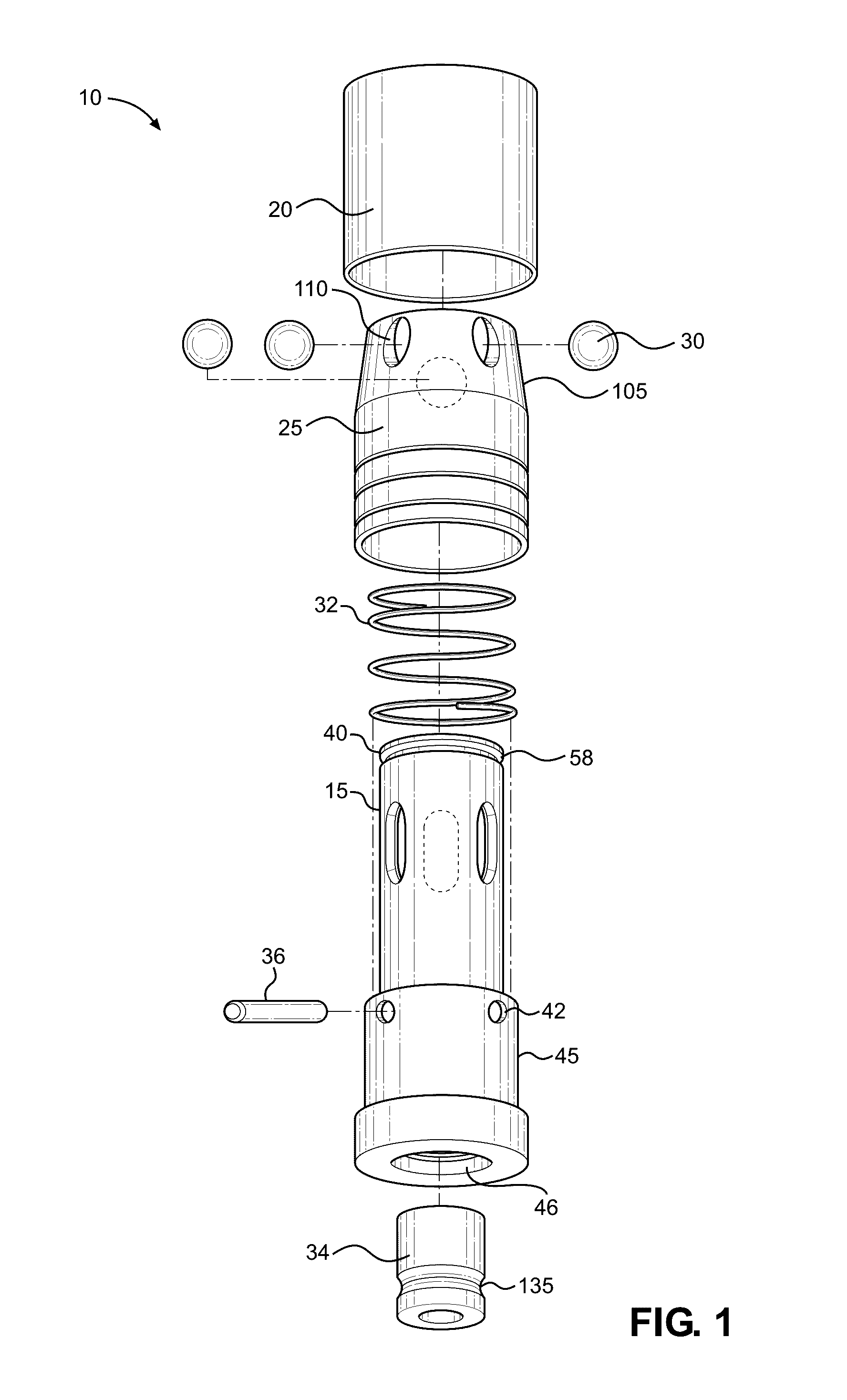
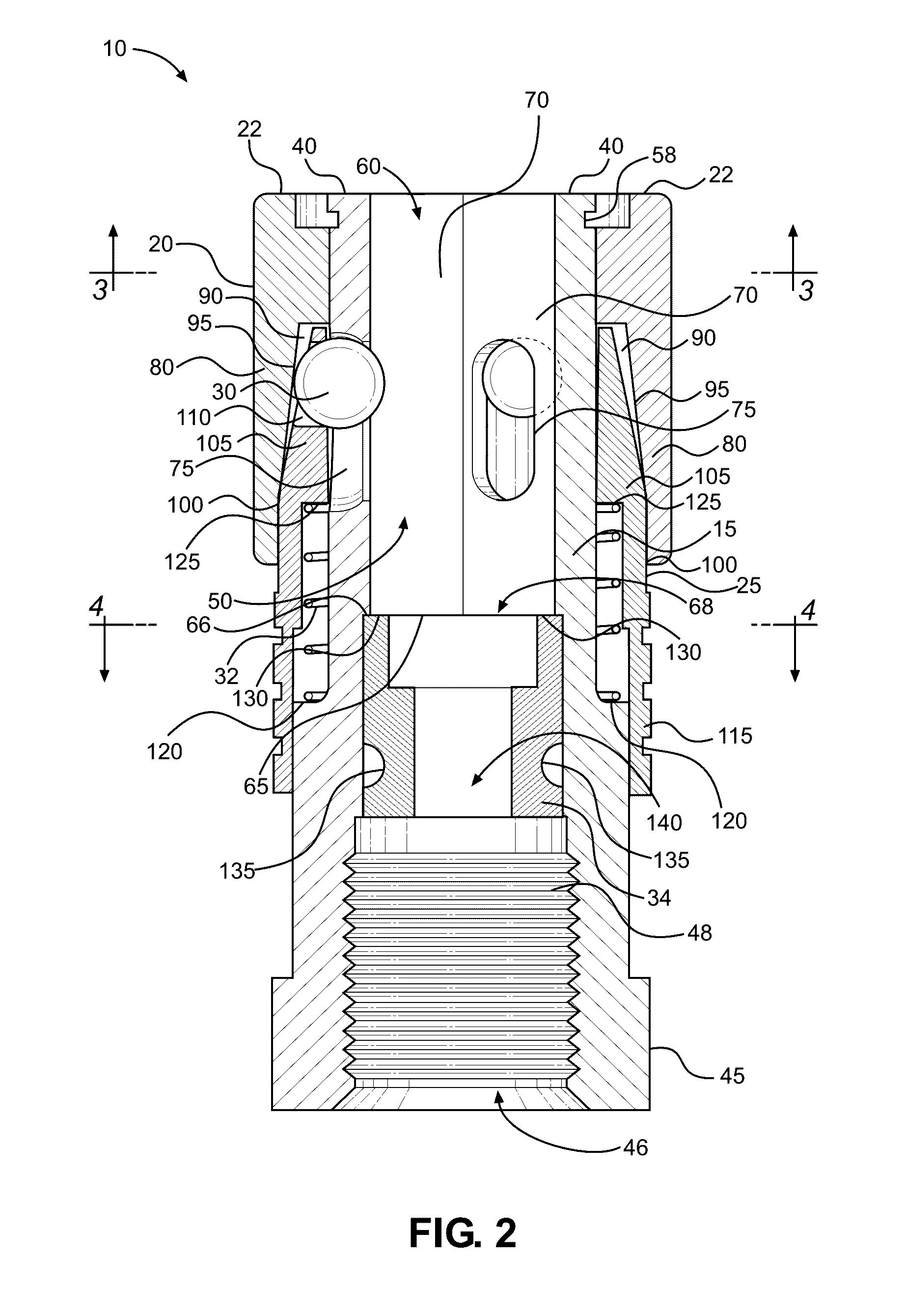
[0017]Referring now to FIGS. 1 and 2, there is shown an exploded view of the drill chuck assembly and a cross-sectional view of the drill chuck assembly along its longitudinal axis, respectively. The present invention comprises a drill chuck assembly 10 configured to receive and retain a drill bit shank. The drill chuck assembly 10 comprises a body 15, a collar 20, a sleeve 25, detent balls 30, a spring 32, a plug 34, and a dowel pin 36.

[0018]The body 15 includes an upper end 40 and a lower end 45. The body 15 comprises a bore 50 having a trilobe profile that is sized and dimensioned to interchangeably receive different types of drill bit shanks, including both triangular drill bit shanks and ...


PUM


Abstract

A drill chuck assembly. The drill chuck assembly includes a rapid change mechanism configured to retain a drill bit shank inserted therein. The drill chuck assembly includes a body having a bore with a trilobe cross-section that is configured to receive a triangular and hexagonally shaped drill bit shank, interchangeably. The bore includes a slot positioned in each lobe that slidably contains a detent ball therein. A collar is affixed annularly around the body and defines a channel extending around the body. A sleeve is slidably mounted around the body. The sleeve includes a tapered end that is slidably disposed within the channel and has circular apertures that are in communication with the slots of the bore for reception of the detent balls. The sleeve is spring biased towards the collar, which forces the detent balls against an angular wall within the channel. The angular wall in turn forces the detent balls laterally towards a center of the bore, thereby exerting a force on a drill bit shank inserted into the bore and preventing the withdrawal of the shank from the bore. When the bias force of the sleeve is counteracted by sliding the sleeve about its longitudinal axis, the detent balls move outwardly along the angular wall, thereby relieving the force exerted onto the shank by the wall and allowing the shank to be withdrawn.

Description

CROSS REFERENCE TO RELATED APPLICATIONS[0001]This application claims the benefit of U.S. Provisional Application No. 62 / 198,324 filed on Jul. 29, 2015. The above identified patent application is herein incorporated by reference in its entirety to provide continuity of disclosure.BACKGROUND OF THE INVENTION[0002]The present invention relates to drill chucks for use with drills or with electric or pneumatic power drivers. More specifically, the present invention relates to a keyless drill chuck assembly having a central bore with a trilobe profile configured to receive a triangular and hexagonally shaped drill bit shank interchangeably and a quick release mechanism configured to receive the drill bit shanks automatically.[0003]There are a variety of different drill chucks involving different tool locking mechanisms. For example, there are jawed chucks, which have many dogs or jaw-like members that are tightened to lock the tool in place. Often the jaws will be tightened or loosened wi...

Claims


Application Information

Patent Timeline
Patent Type & Authority Patents(United States)
IPC IPC(8): B23B31/22B23B31/107B23B31/20
CPCB23B31/22B23B31/1071B23B2231/0224B23B2260/12B23B31/208Y10S279/905Y10T279/17145Y10T279/17752B23B31/005B23B2231/022B23B2231/0232B23B2231/38
Inventor HOMOLA, KAARLE
Owner HOMOLA KAARLE
Why Eureka
Try Eureka