High-speed, low runout spindle assembly

a spindle assembly, high-speed technology, applied in the direction of chucks, mechanical equipment, manufacturing tools, etc., can solve the problems of low use value of end mills, low cost of options, and significant reduction of lifetim

Pending Publication Date: 2022-02-24
ZIPPY ROBOTICS INC
View PDF29 Cites 0 Cited by
  • Summary
  • Abstract
  • Description
  • Claims
  • Application Information

AI Technical Summary

Benefits of technology

[0007]According to yet another aspect of the present invention, a high-speed, low runout spindle assembly is provided. The spindle assembly includes a friction drive wheel configured to be coupled to an output shaft of a motor. The friction drive wheel is configured and disposed to directly contact a shank of a bit. An upper bearing and a lower bearing are arranged coaxially along a vertical direction and are configured to contact the shank of the bit. A central bore of the upper bearing and a central bore of the lower bearing are aligned and dimensioned to accept the shank of the bit. A bit clamp assembly includes a clamp bearing having a central through-hole dimensioned to accept a lower portion of the shank of the bit. The bit clamp assembly is configured to hold the bit in contact with the upper bearing and the lower bearing. A housing encloses the friction drive wheel and the upper bearing and the lower bearing. The housing includes a first magnet and a second magnet configured to magnetically couple with respective magnets disposed on a top surface of the bit clamp assembly. The first magnet and the second magnet are coupled to respective compression springs configured to apply an upward force to securely hold the bit clamp assembly and pre-load the lower bearings.

Problems solved by technology

However, with an end mill diameter of only 5-mils, as would be necessary for fine detail milling, runout of 1 to 5 mils will likely cause the end mill to snap on contact with the material in the worst case, or in the best case suffer from uneven load on the end mill's teeth and rapid wear, leading to a significantly reduced lifetime, to the point where little useful work can be done with the end mill.
Commercial options for high speed, low runout spindles exist, however, these options can be quite expensive.
Moreover, even these high speed, low runout spindles may not have a static runout that is as low as 0.0001-inch.

Method used


Image

  • High-speed, low runout spindle assembly
  • High-speed, low runout spindle assembly
  • High-speed, low runout spindle assembly

Examples


Embodiment Construction

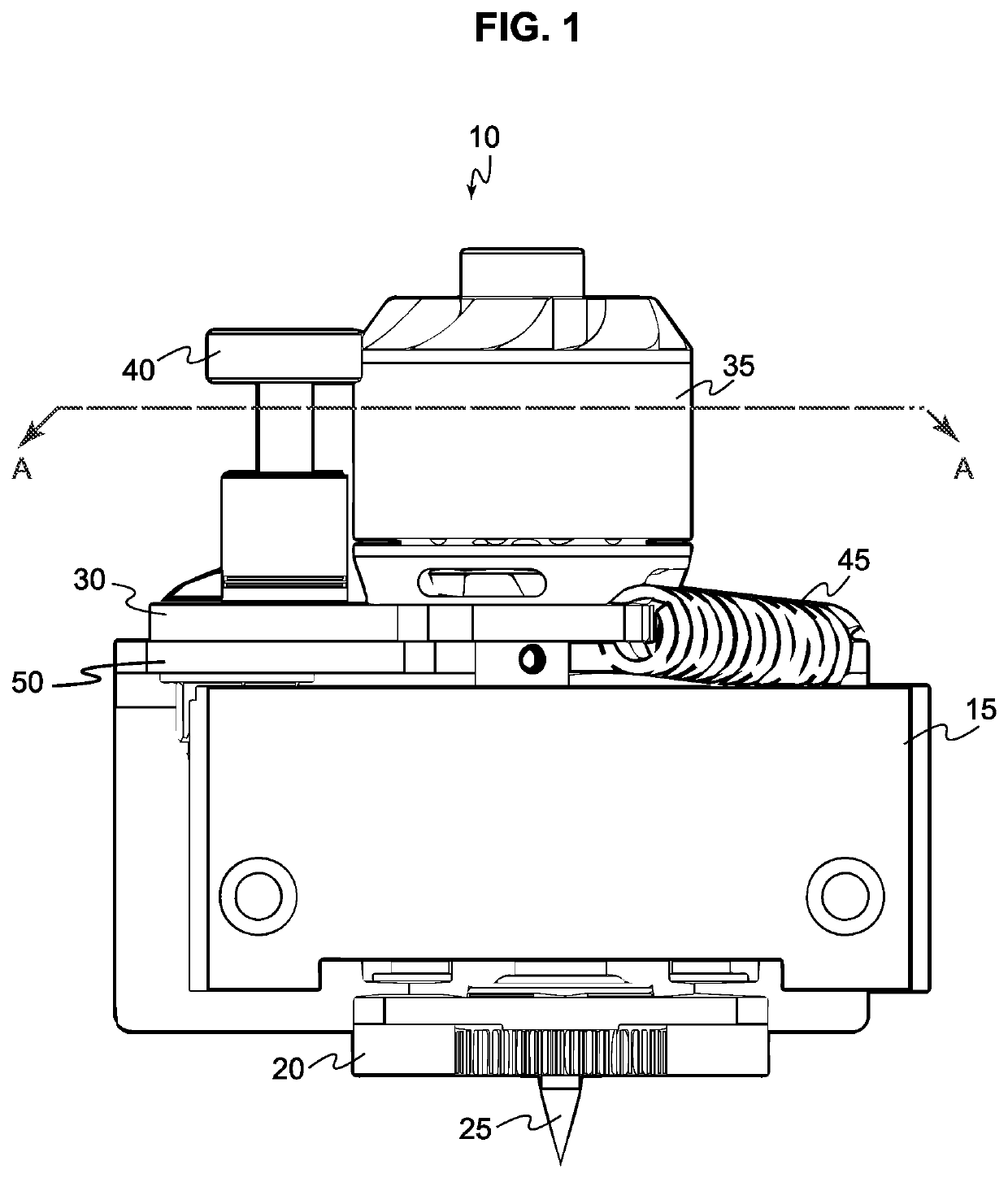
[0018]Some embodiments of the present invention can have static run-outs of about 0.0001 inches and be manufactured at a much-reduced cost. While commercial solutions provide high load capacities during milling and drilling, this is not a factor for applications such as printed circuit board (PCB) milling where the engraving is just a few thousandths of an inch into the material.

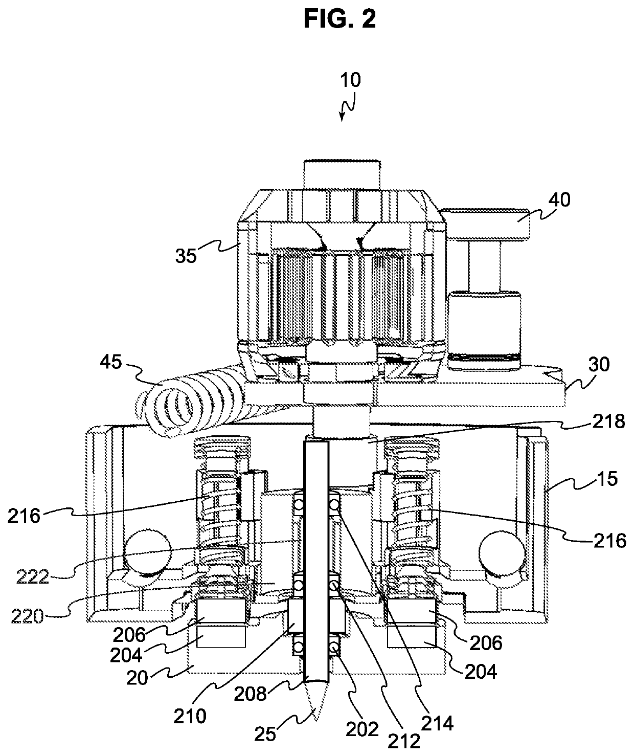
[0019]Embodiments of the present invention, unlike conventional spindles, hold bits, such as end mills and drill bits, for example, without using a collet or other chuck assemblies. Instead, the end mill or drill bit can be inserted directly through the inner bore of the bearings. It is generally understood that end mills are used for routing while drill bits are used for drilling. However, within the context of the present invention the term “bit” is used to encompass all such rotating cutting tools, and thus the use of one term or the other hereinafter should not be construed to limit the so-referred compo...


PUM

PropertyMeasurementUnit
diameteraaaaaaaaaa
forceaaaaaaaaaa
magnetic fieldaaaaaaaaaa

Abstract

A high-speed low runout spindle assembly is provided. The spindle assembly includes a friction drive wheel configured to be coupled to an output shaft of a motor. The friction drive wheel is configured and disposed to directly contact a shank of a bit. A set of bearings is configured to contact the shank of the bit. A bit clamp assembly includes a clamp bearing having a central through-hole dimensioned to accept a lower portion of the shank of the bit. The bit clamp assembly is configured to hold the bit in contact with the set of bearings.

Description

CROSS-REFERENCE TO RELATED APPLICATION[0001]This application claims priority to U.S. Provisional Patent Application No. 63 / 067,894, filed on Aug. 20, 2020, which is incorporated herein by reference in its entirety.BACKGROUNDTechnical Field[0002]The present invention relates to spindles for computerized numerical control (CNC) machines, and more particularly to a high speed, low runout spindle for small diameter end mills used in CNC machines.Background Information[0003]A generic, hobby spindle of the type used in consumer-grade desktop CNC machines for cutting wood can have a radial runout of 1 to 5 mils (0.001 to 0.005 inches). However, with an end mill diameter of only 5-mils, as would be necessary for fine detail milling, runout of 1 to 5 mils will likely cause the end mill to snap on contact with the material in the worst case, or in the best case suffer from uneven load on the end mill's teeth and rapid wear, leading to a significantly reduced lifetime, to the point where littl...

Claims


Application Information

Patent Timeline
Patent Type & Authority Applications(United States)
IPC IPC(8): F16C25/08F16C19/54B23B31/00B23Q1/26
CPCF16C25/08F16C19/54F16C2322/39B23Q1/265B23B31/005B23B31/28B23Q2017/001B23Q1/70F16C25/086B23Q5/10
Inventor TUCCIO, ROCCO J.
Owner ZIPPY ROBOTICS INC
Why Eureka
Try Eureka