
Remotely-operable reciprocating compactor

a reciprocating and compactor technology, applied in the direction of roads, construction, foundation engineering, etc., can solve the problems of long-term effects of operators who regularly use such equipment over extended periods, and are potentially very hazardous

Active Publication Date: 2017-02-28
WILLIAMS JASON A
View PDF20 Cites 11 Cited by
  • Summary
  • Abstract
  • Description
  • Claims
  • Application Information

AI Technical Summary

Benefits of technology

The present patent talks about an apparatus, device and method for a remotely-operable percussion compactor. The compactor includes a primary power source, electric motors, reaction wheels, an inertial measurement unit, a remote control interface, and a controller. The controller receives command signals from the remote control interface and uses feedback signals from the inertial measurement unit to set desired operating conditions for the electric motors. The goal of this invention is to provide a compact, efficient, and effective tool for pneumatic and percussion compaction of materials. The apparatus can be controlled from a remote location, making it easier to operate and manage.

Problems solved by technology

A principal drawback of such solutions is that they still require the operator to maintain contact with the percussive soil compactor for extended periods of time, during which he or she continues to absorb vibrations.
Even though such vibrations may be reduced in magnitude, the long-term effects on operators who regularly use such equipment over extended periods is unknown at best—and potentially very hazardous.

Method used


Image

  • Remotely-operable reciprocating compactor
  • Remotely-operable reciprocating compactor
  • Remotely-operable reciprocating compactor

Examples


Embodiment Construction

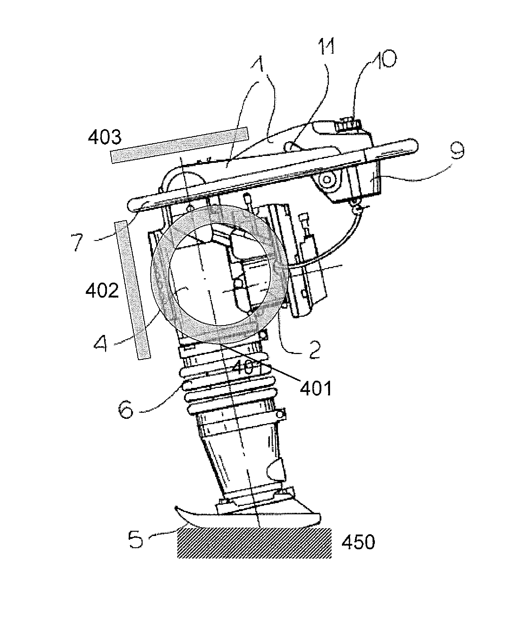
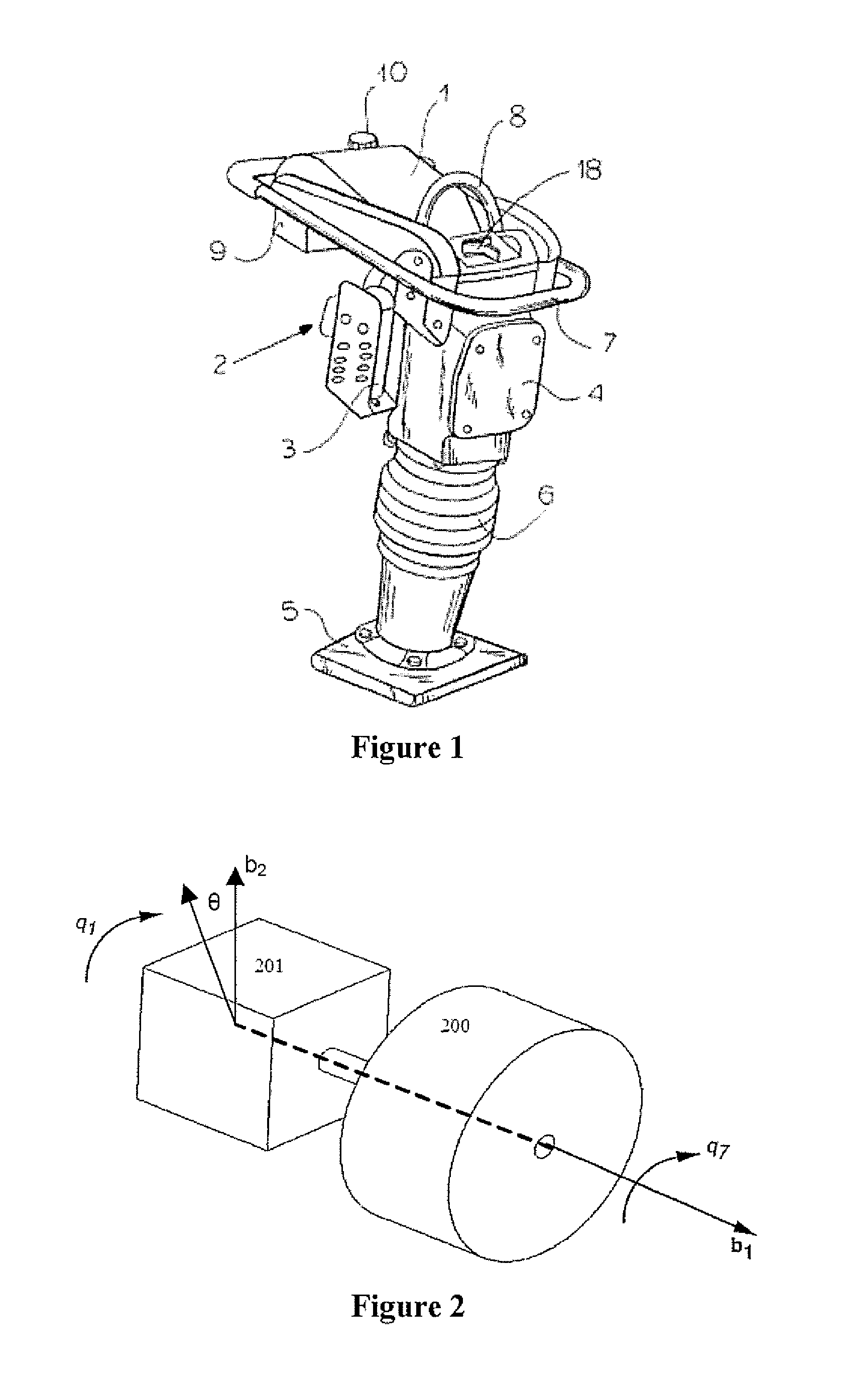
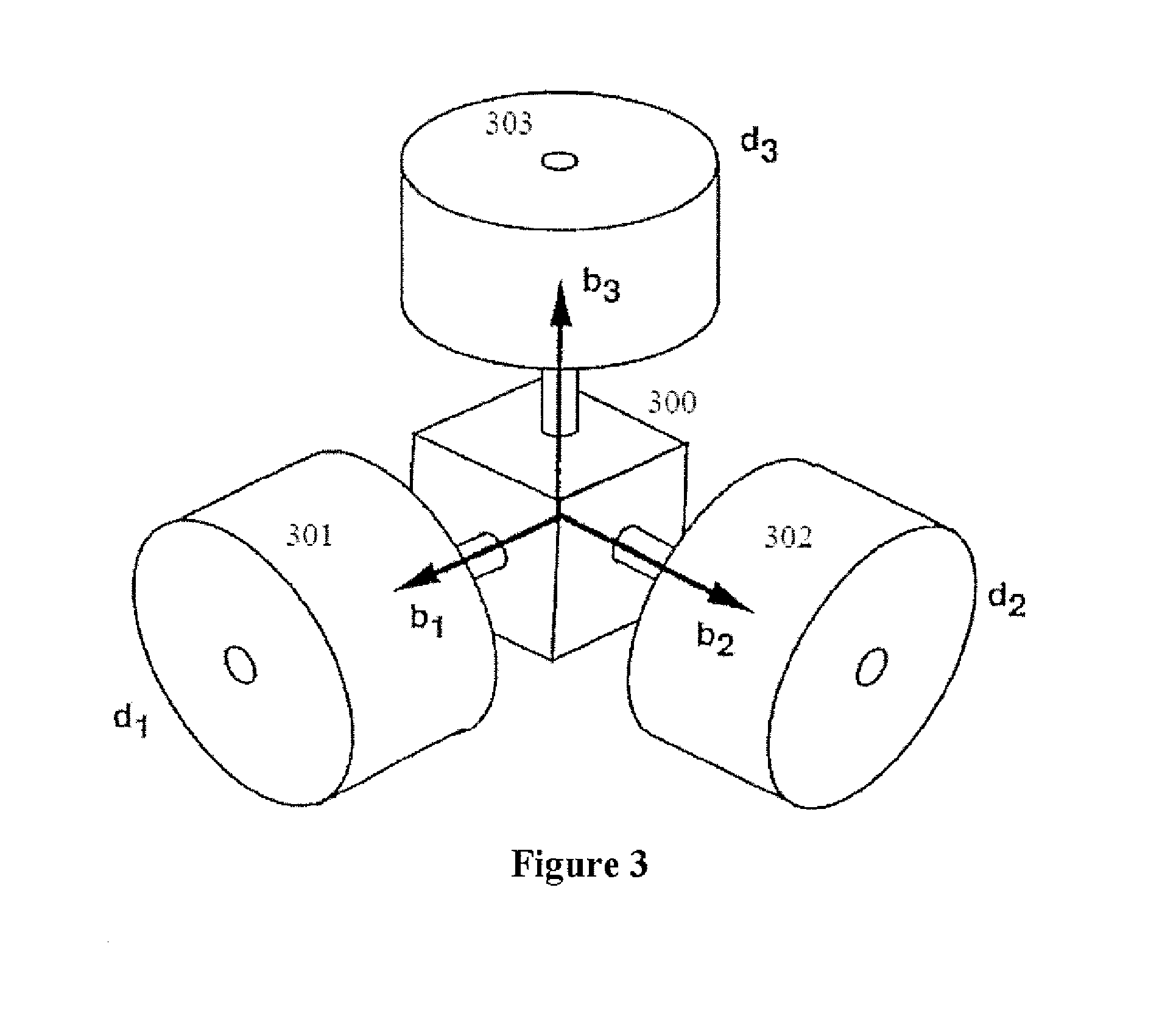
[0007]Accordingly, to address at least some of such issues and / or problems, certain exemplary embodiments of apparatus, devices, and methods according to the present disclosure include a remotely-operable percussion compactor, comprising: a primary power source; a plurality of electric motors, each coupled to the primary power source and attached to the body of the percussion compactor; a plurality of reaction wheels coupled to respective ones of the electric motors; an inertial measurement unit; a remote control interface; and a controller configured by execution of programmable instructions to: receive one or more commands from the remote-control interface; receive a feedback signal from the inertial measurement unit; and set a desired operating condition for at least one of the electric motors based on at least one of the feedback signal and the one or more commands. In certain exemplary embodiments, the primary power source comprises an internal combustion engine and the electri...


PUM


Abstract

Embodiments of the present disclosure include a remotely-operable percussion compactor comprising: a primary power source; a plurality of electric motors coupled to the primary power source and attached to the compactor body; a plurality of reaction wheels coupled to respective electric motors; an inertial measurement unit (IMU); a remote control interface; and a controller configured to: receive one or more commands from the remote-control interface and a feedback signal from the IMU, and set a desired operating condition for at least one of the electric motors based on at least one of the feedback signal and the one or more commands. In some embodiments, the controller can be configured to determine an angular disturbance relative to at least one rotational axis of the compactor; and set the desired operating condition for one or more electric motors to generate a reactive force to at least partially counteract the angular disturbance.

Description

FIELD OF THE DISCLOSURE[0001]The present application relates generally to the field of percussion soil compactors, also known as rammers or tampers, and more specifically to systems, methods, and apparatus for improving the user safety and performance of reciprocating soil compactors by enabling such devices to be operated remotely without direct contact by a user.BACKGROUND INFORMATION[0002]Percussion compactors (also known as rammers and tampers) are well known in the construction industry and are used to compact soil and other loose materials in a variety of construction and excavation operations. Such devices are typically manually operated by a single operator. A percussion rammer is distinguishable from a vibration (or vibratory) compactor in terms of both amplitude and frequency of operation. A percussion rammer may operate with a vertical amplitude of approximately 2-3 inches (50-75 mm) and a frequency of about 600-800 cycles per minute (cpm). A vibratory compactor, on the o...

Claims


Application Information

Patent Timeline
Patent Type & Authority Patents(United States)
IPC IPC(8): E02D3/00E02D3/074E02D3/046E01C19/32E01C19/35
CPCE02D3/074E02D3/046E01C19/32E01C19/35
Inventor WILLIAMS, JASON A.
Owner WILLIAMS JASON A
Learn More