Supercharge Your Innovation With Domain-Expert AI Agents!

Fluid flow control valve and actuator

a technology of flow control valve and actuator, which is applied in the direction of valve housing, mechanical equipment, transportation and packaging, etc., can solve the problems of inability to quickly test and quickly install the ball valve and the pedestal in a new aircraft, and the existing arrangement of actuators

Inactive Publication Date: 2017-02-28
AIRBUS OPERATIONS LTD
View PDF18 Cites 1 Cited by
  • Summary
  • Abstract
  • Description
  • Claims
  • Application Information

AI Technical Summary

Benefits of technology

The invention provides an improved arrangement for accessing an actuator and fluid control valve without entering the wet side of a fuel tank. It allows for the installation of a blind canister in an opening in the fuel tank, and the connection of ducts or pipes to the canister. The valve housing and valve member may be removed for repair or replacement without disturbing the fuel tank. The valve or sluice prevents the ingress of foreign matter and helps with removal of the actuators.

Problems solved by technology

Maintenance and repair of such valves can be problematic.
Furthermore the existing arrangement of actuator, ball valve and pedestal cannot be quickly assembled and tested in a new aircraft.

Method used


Image

  • Fluid flow control valve and actuator
  • Fluid flow control valve and actuator
  • Fluid flow control valve and actuator

Examples


Embodiment Construction

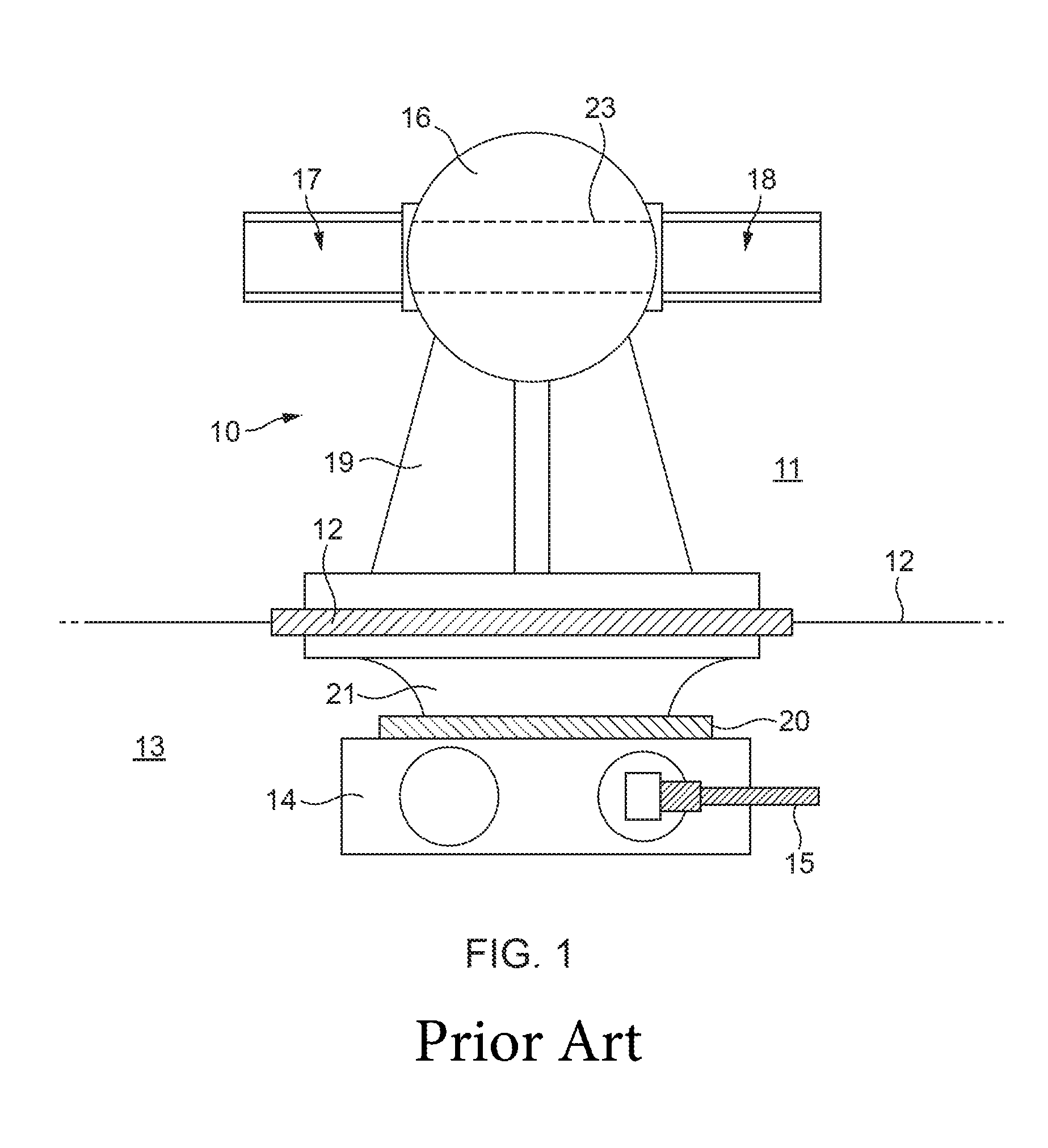
[0027]With reference to FIG. 1, a prior art valve assembly 10 is located on the wet side 11 of a fuel tank wall 12. On the dry side 13, typically in a closed compartment, is provided an electrical actuator 14 for the valve assembly 10; the actuator 14 has the usual power and control connection 15, typically part of a wiring harness.

[0028]The valve assembly comprises a housing 16 containing a ball valve or the like, by which communication between pipe connections 17, 18 can be opened and closed. The pipe connections consist of any suitable fluid coupling, for example coupled (bolted) pipe flanges or compression joints.

[0029]A pedestal 19 is provided to space the housing away from the tank wall 12, and is fixed to the tank wall by any suitable kind of fastener, for example a row of threaded fasteners.

[0030]The actuator 14 is attached to a mounting 21 which is in turn affixed to the tank wall 12; a V band clamp 20 may be used. A shaft of the actuator (not shown) passes through the tank...


PUM


Abstract

A fluid flow control valve is housed within a canister (31) which is semi-permanently fixed in the wall (12) of a fuel tank, and has pipe connections (17, 18). The movable valve parts, including a valve sub-assembly (32, 33) and an electrical actuator (34), may be removed without requiring access to the fuel tank.

Description

RELATED APPLICATIONS[0001]This application is the U.S. national phase of International Application No. PCT / GB2013 / 052694, filed 15 Oct. 2013, which designated the U.S. and claims priority to GB Patent Application No. 1218764.7, filed 18 Oct. 2012, the entire contents of each of which are hereby incorporated by reference.BACKGROUND OF INVENTION[0002]This invention relates to a valve and actuator, suitable for controlling flow of fluids in a duct.[0003]Fluid flow valves are well known and generally comprise a housing defining an inlet and an outlet, and a movable valve member within the housing, having an internal through passageway to connect the inlet and outlet. The valve member is pivotable or rotatable between an open condition in which the inlet and outlet is connected and a closed condition in which the inlet and outlet are not connected.[0004]Typically the valve member has a pivot axis perpendicular to the internal through passage, which is straight. Thus movement between the ...

Claims


Application Information

Patent Timeline
Patent Type & Authority Patents(United States)
IPC IPC(8): F16K25/00F16K43/00F16K3/312F16K27/06
CPCF16K3/312F16K27/06F16K43/00Y10T137/6011
Inventor HASKINS, RICHARDJONES, JOHN
Owner AIRBUS OPERATIONS LTD
Features
  • R&D
  • Intellectual Property
  • Life Sciences
  • Materials
  • Tech Scout
  • Unparalleled Data Quality
  • Higher Quality Content
  • 60% Fewer Hallucinations
Learn More