Perfected washing plant

a technology of washing machine and washing plate, applied in the field of washing machine, can solve the problems of large installation size and excessive bulk

Active Publication Date: 2017-03-07
STEELCO
View PDF9 Cites 1 Cited by
  • Summary
  • Abstract
  • Description
  • Claims
  • Application Information

AI Technical Summary

Benefits of technology

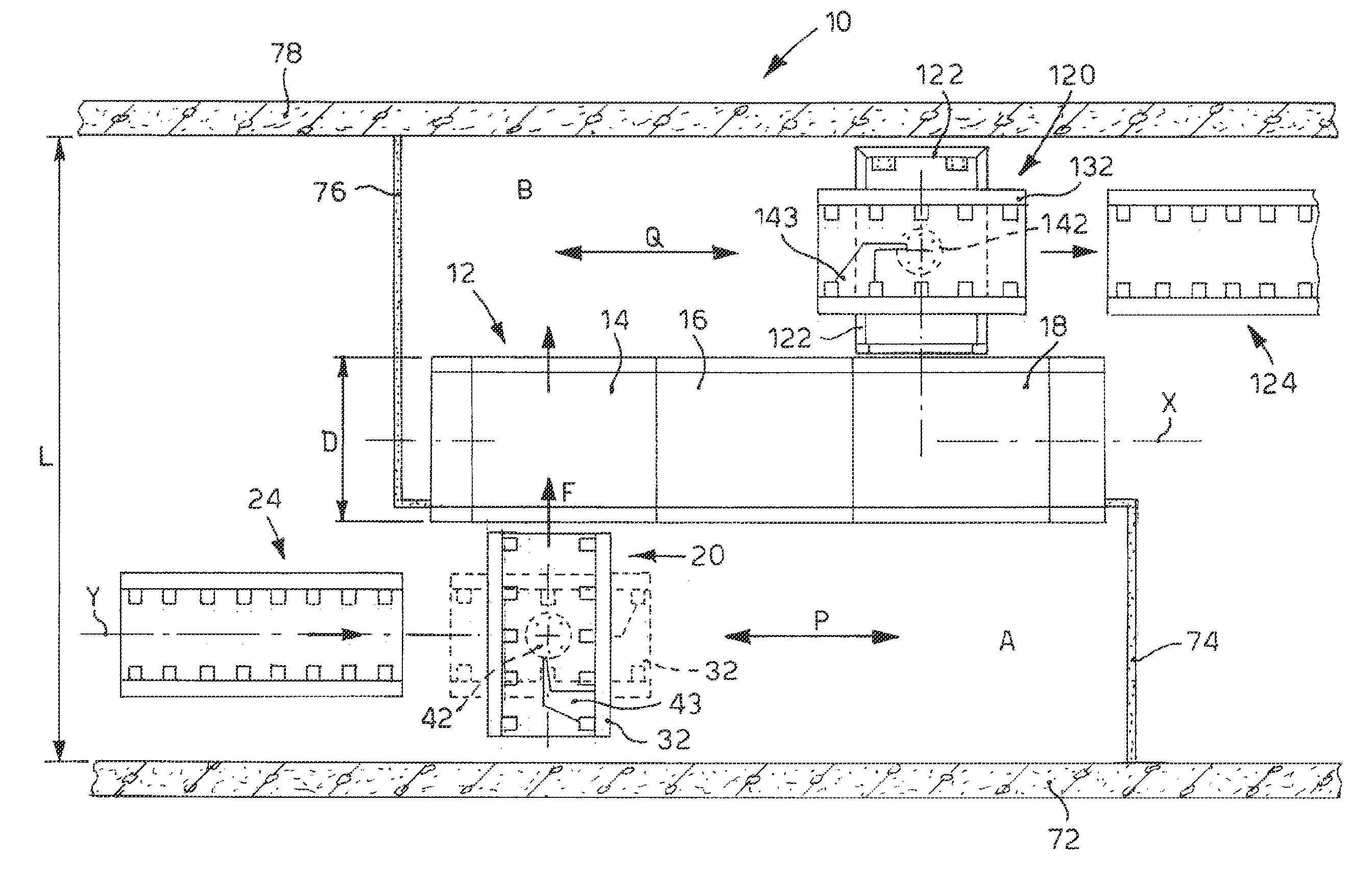
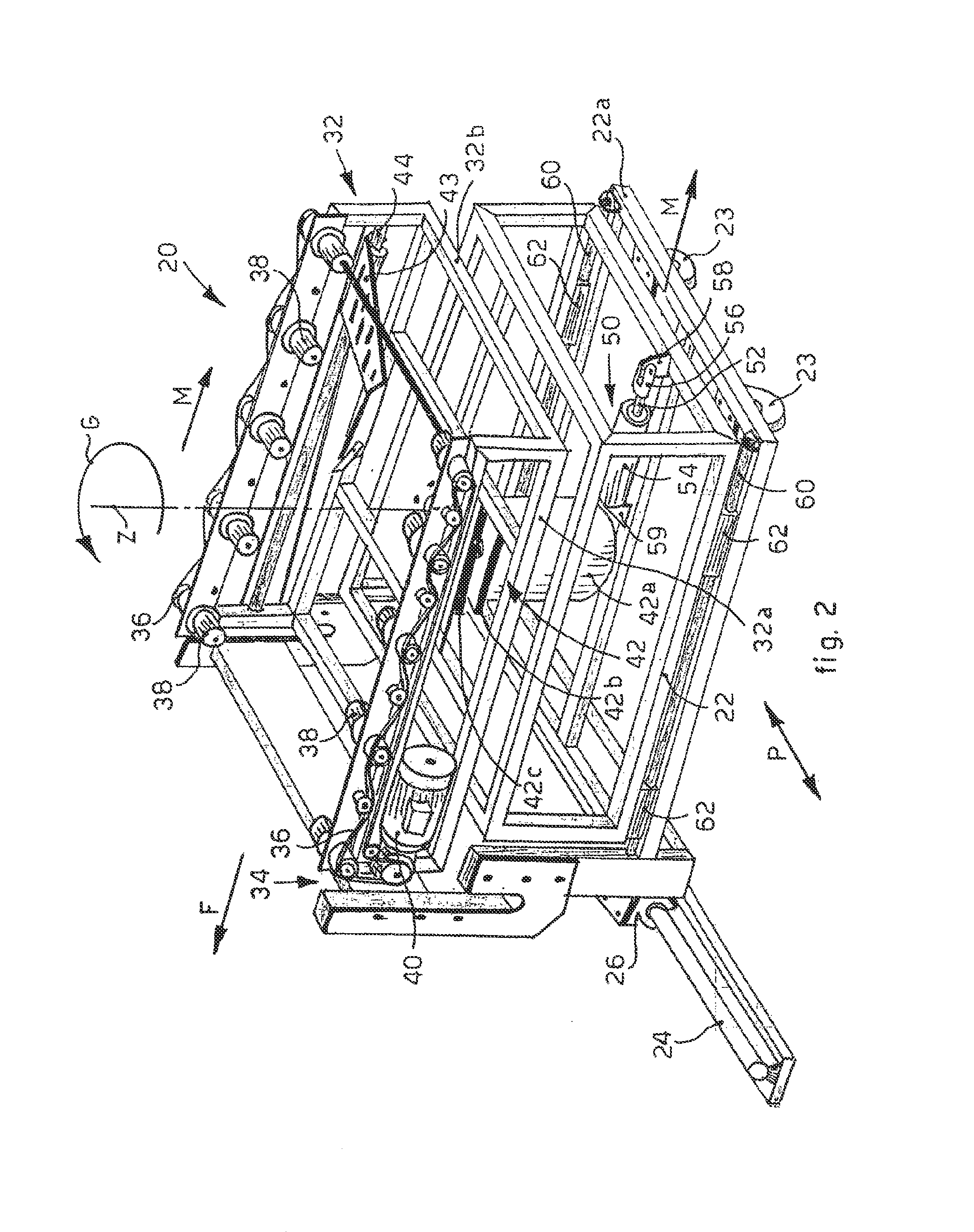
[0027]In this way, before rotating the rotating upper frame with respect to the lower frame, it is possible to translate linearly backward the combination formed by the lower frame and the rotating upper frame so as to create the space needed to rotate the bulk of the rotating upper frame without it interfering with other front parts of the slider or the washer machines. The rotating upper frame, after being moved backward in the fourth position, can be rotated from the first to the second position without interfering with other parts of the slider or the machines, and then can be loaded with the objects to be washed received from the transport means, again rotated from the second to the first position and subsequently made to advance again toward the washer machines in the third position.
[0028]It is thus possible to install the plant even in very narrow spaces or with an elongated conformation, since the bulk of the fixed movement means, normally disposed between the pre-wash and the washer machines perpendicular to the axis of alignment of the latter, is completely eliminated.
[0029]In fact, by disposing the movement means with an operating direction parallel to the axis of alignment of the washer machines and in direct cooperation with the movement path of the translator slider, it is possible to load the objects easily onto the translator slider, where the rotating upper frame has been suitably rotated in the direction coordinated with the movement means and, subsequently, to direct the objects to the washer machines, by means of the translator slider, where the rotating upper frame has again been rotated in the direction coordinated with the direction of feed toward the washer machines.

Problems solved by technology

One disadvantage of known washing plants is that, in order to carry out at least the pre-wash and the washing and heat-disinfection, they have very large installation sizes.
However, this known solution too, in particular contexts where the installation spaces of the plant are narrow or not optimal, may suffer from an excessive bulk.

Method used


Image

  • Perfected washing plant
  • Perfected washing plant
  • Perfected washing plant

Examples


Embodiment Construction

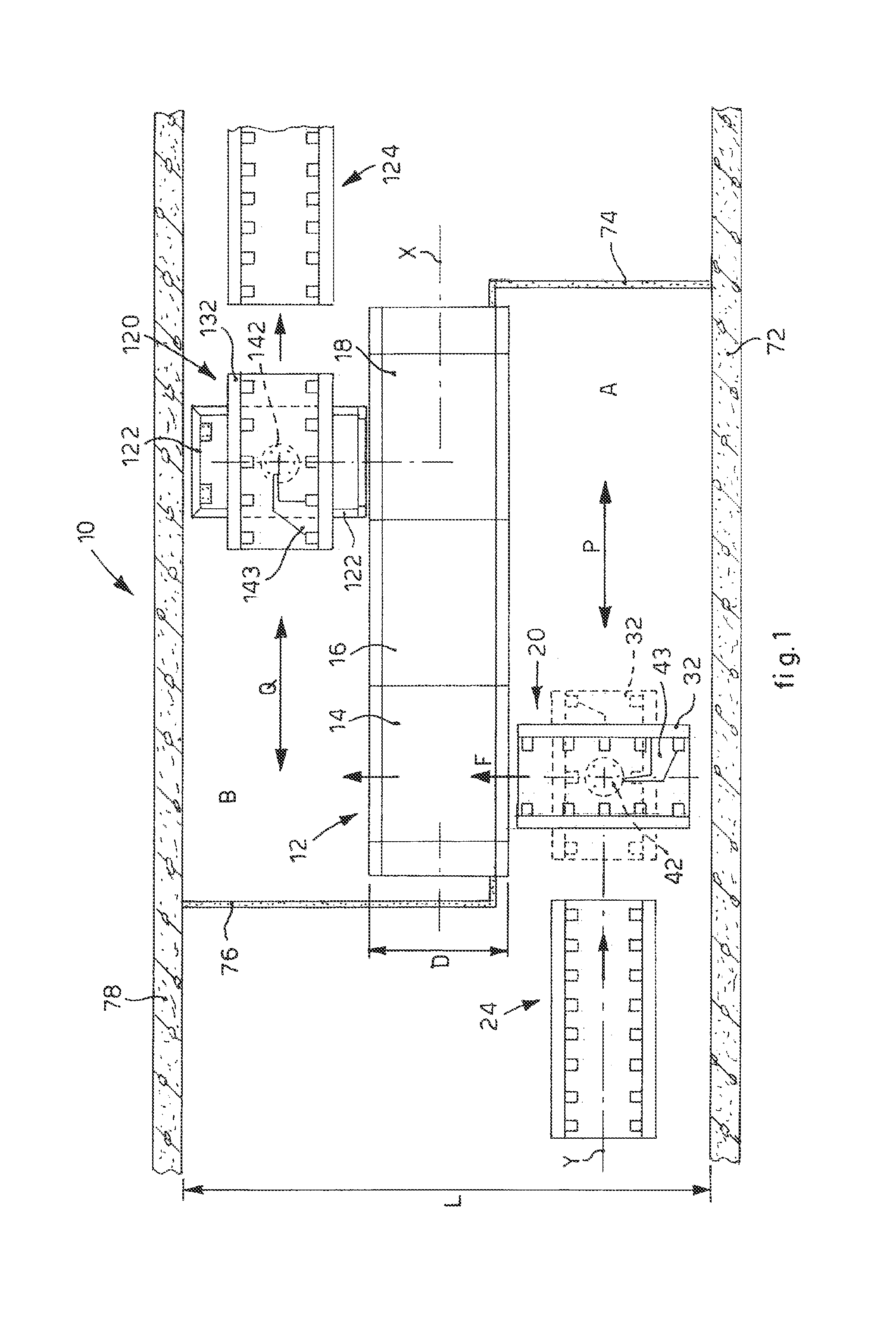
[0043]With reference to FIG. 1, a washing plant 10 according to the present invention is used to effect the complete treatment of pre-washing, washing, heat-disinfection and sterilization of objects, such as instruments from hospital wards, operating rooms, laboratories and the pharmaceutical industry, generally contained and transported in suitable racks.

[0044]The plant 10 in particular is configured in three sectors divided by separation means 72, 74, 76, 78, for example walls, possibly put selectively in communication by a pass-through, in particular a dirty sector A, to receive the dirty instruments, a clean sector B, downstream of the heat-disinfection, and a sterile sector, downstream of the sterilization.

[0045]The expression “separation means” means both separating walls proper, and also the bodies of other machines or apparatuses, and also paths needed for moving the instruments or other objects to be washed. For example, it is possible to provide two opposite main separatio...


PUM

PropertyMeasurementUnit
temperatureaaaaaaaaaa
rotationaaaaaaaaaa

Abstract

A washing plant (10) comprises a battery (12) of washing and heat-disinfection machines (14, 16, 18) disposed along an alignment axis (X), able to operate in parallel with respect to each other in order to effect the washing and heat-disinfection, at least a translator slider (20) mobile in an automatic manner parallel to the alignment axis (X) in a front position to said battery (12), which receives the objects to be washed and both transports them in correspondence to the entrance of one of the machines (14, 16, 18) selected on each occasion depending on the washing program set or depending on availability, and moves them inside the desired machine (14, 16, 18) in a direction of feed (F) substantially perpendicular to said alignment axis (X), transport means (24) being provided to direct the objects to be washed toward the translator slider (20) operating in a direction of transport (Y) substantially parallel to said alignment axis (X). The translator slider (20) comprises a lower frame (22) associated slidably to the battery (12) of machines (14, 16, 18), in order to allow the movement parallel to the alignment axis (X), and a rotating upper frame (32) suitable to support the objects to be washed and which comprises movement means (34) to move the objects inside the desired machine (14, 16, 18) in said direction of feed (F), said rotating upper frame (32) being rotatably coupled to the lower frame (22) by means of rotation means (42), so as to be able to be rotated between a first position, aligned to said direction of transport (Y) of the transport means (24) and in which it is configured to receive the objects from said transport means (24), and a second position, aligned to said direction of feed (F) to direct the objects inside the desired machine (14, 16, 18).

Description

FIELD OF THE INVENTION[0001]The present invention concerns a washing plant for objects, for example medical instruments for hospital wards, operating rooms, laboratories and the pharmaceutical industry, typically contained in a rack, comprising a first battery of washer machines, aligned in a desired first direction so as to operate in parallel, and comprising a translator slider mobile in the first direction so as to feed one or more racks containing objects to be washed to one of the washer machines selected on each occasion according to the washing program set, or according to availability. The racks containing the objects to be washed supplied to the translator slider typically come from transport and feed means, which can be automatic, semi-automatic or manual, generally associated with a second battery of pre-wash machines aligned on a determinate axis of alignment so as to operate in series.BACKGROUND OF THE INVENTION[0002]It is known that, usually, hospital structures are pr...

Claims


Application Information

Patent Timeline
Patent Type & Authority Patents(United States)
IPC IPC(8): B08B1/02B08B13/00B08B3/04A61L2/24A61L2/04B08B7/04
CPCB08B7/04A61L2/04A61L2/24B08B3/04B08B13/00A61L2202/16A61L2202/17A61L2202/24
Inventor ZARDINI, FABIO
Owner STEELCO
Why Eureka
Try Eureka