

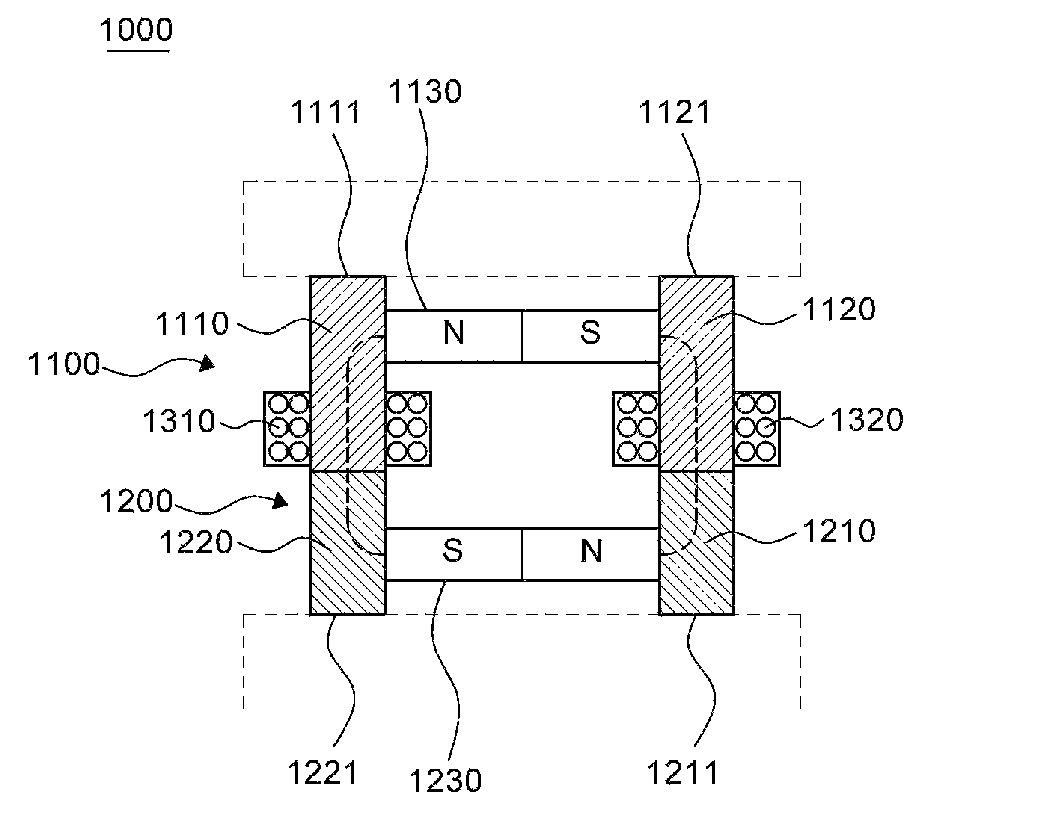
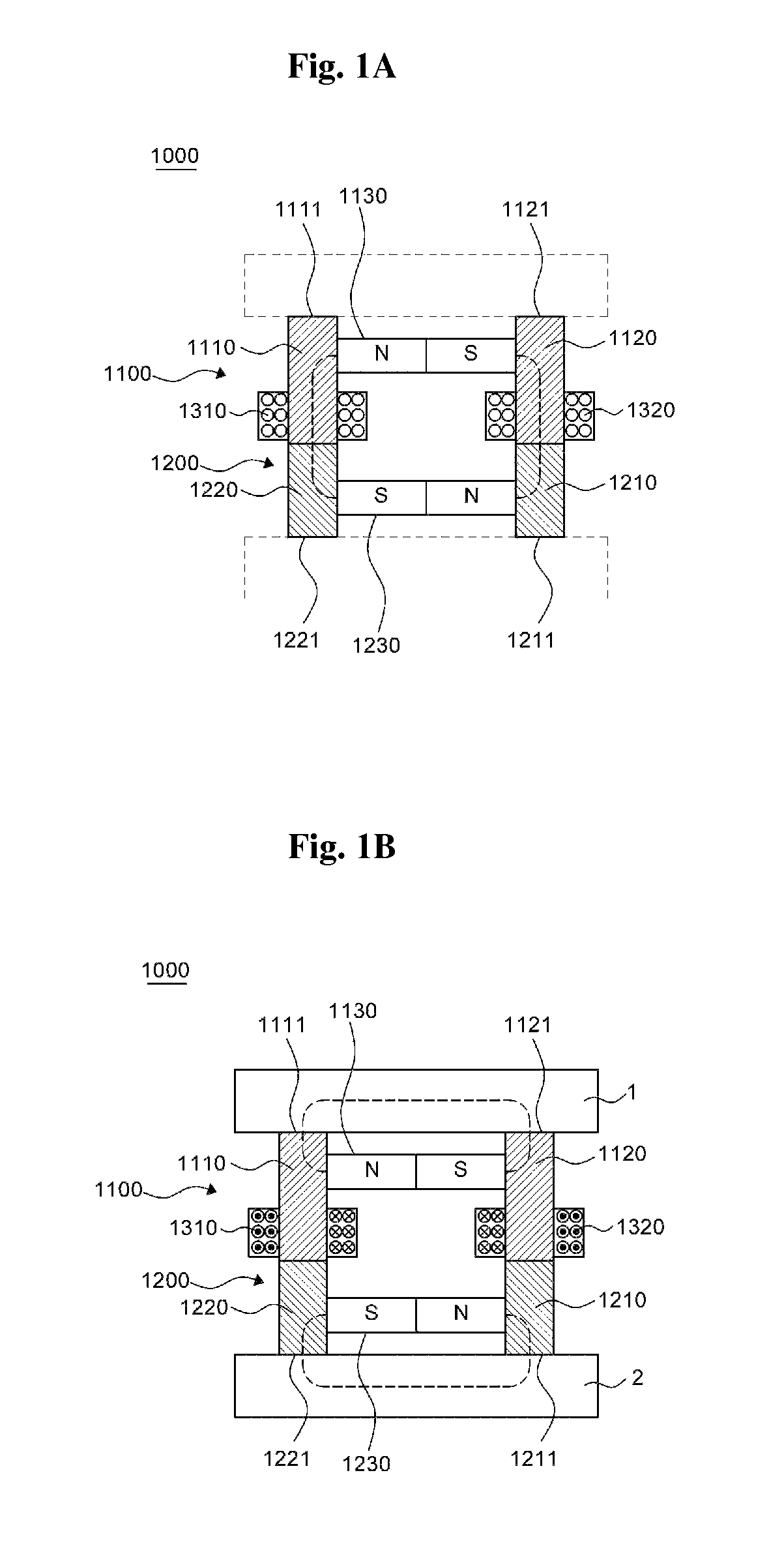
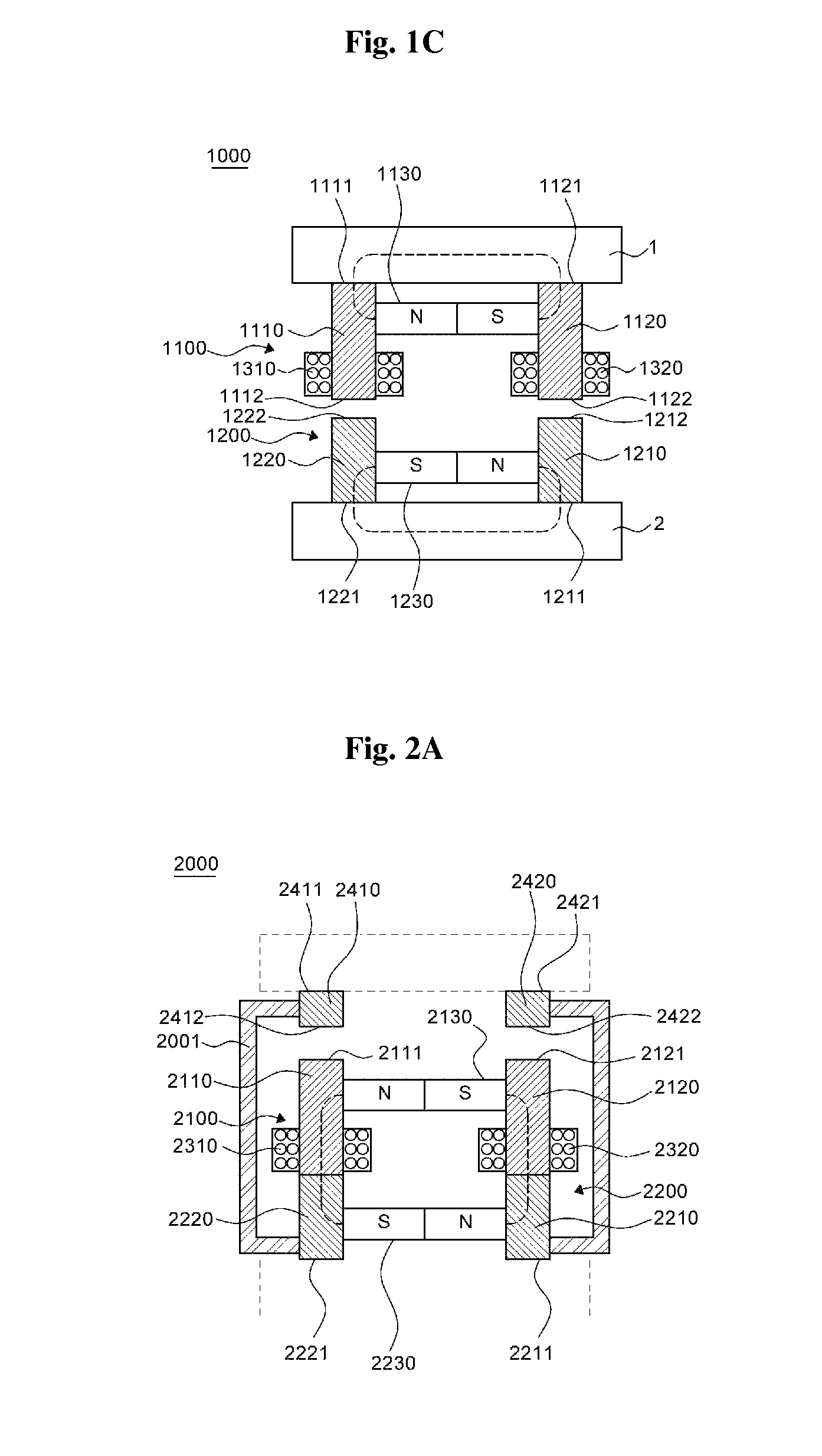
Magnetic substance holding device
a holding device and magnetic substance technology, applied in the direction of magnets, magnet bodies, manufacturing tools, etc., can solve the problems of difficult control of magnetic flux and harm to usability, and achieve the effects of reducing residual magnetism, strong holding force, and easy switching between holding and detaching
- Summary
- Abstract
- Description
- Claims
- Application Information
AI Technical Summary
Benefits of technology
Problems solved by technology
Method used
Image

Examples
Embodiment Construction
[0047]Advantages and features of the present invention and methods to achieve them will become apparent from the descriptions of exemplary embodiments herein below with reference to the accompanying drawings. However, the present invention is not limited to exemplary embodiments disclosed herein but may be implemented in various different forms. The exemplary embodiments are provided for making the disclosure of the present invention thorough and for fully conveying the scope of the present invention to those skilled in the art. It is to be noted that the scope of the present invention is defined only by the claims.
[0048]As used herein, a phrase “an element A on an element B” refers to that the element A may be disposed directly on the element B and / or the element A may be disposed indirectly on the element B via another element C.
[0049]Terms such as first, second, etc. are used to distinguish arbitrarily between the elements such terms describe and these terms are not necessarily i...
PUM
| Property | Measurement | Unit |
|---|---|---|
| magnetic flux | aaaaa | aaaaa |
| current | aaaaa | aaaaa |
| magnetic fluxes | aaaaa | aaaaa |
Abstract
Description
Claims
Application Information