Busway joint coupling having a splice plate with a longitudinal rib

a busway joint and longitudinal rib technology, applied in the field of electric busways, can solve the problems of non-standard or custom length, and fixed length sections that do not match the specific length required

Active Publication Date: 2017-03-07
ABB (SCHWEIZ) AG
View PDF53 Cites 9 Cited by
  • Summary
  • Abstract
  • Description
  • Claims
  • Application Information

AI Technical Summary

Problems solved by technology

In many cases, the fixed-length sections do not match the specific length required for a given installation.
As a result, custom length busway joints may be manufactured, adding significant cost and time to the installation.
For example, installers typically order non-standard or custom length busway sections or joints to complete an installation.

Method used


Image

  • Busway joint coupling having a splice plate with a longitudinal rib
  • Busway joint coupling having a splice plate with a longitudinal rib
  • Busway joint coupling having a splice plate with a longitudinal rib

Examples


Embodiment Construction

[0027]As used in this description and in the claims which follow, the term “phase” shall be taken to include all conductors in different runs of any particular busway, bus duct, or busway joint which carry the same electrical phase, and including those conductors which are used to carry any neutral or ground phase.

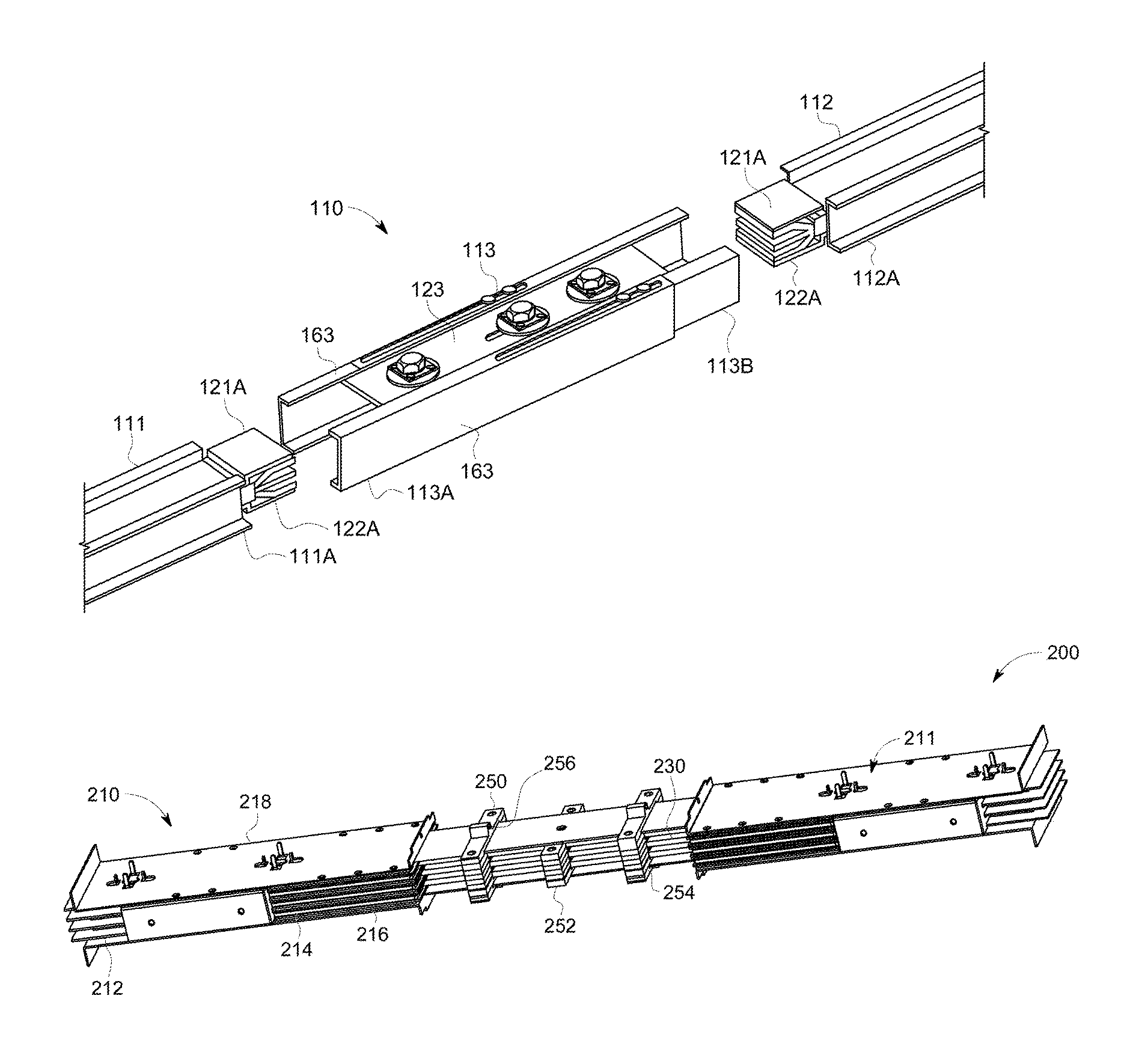
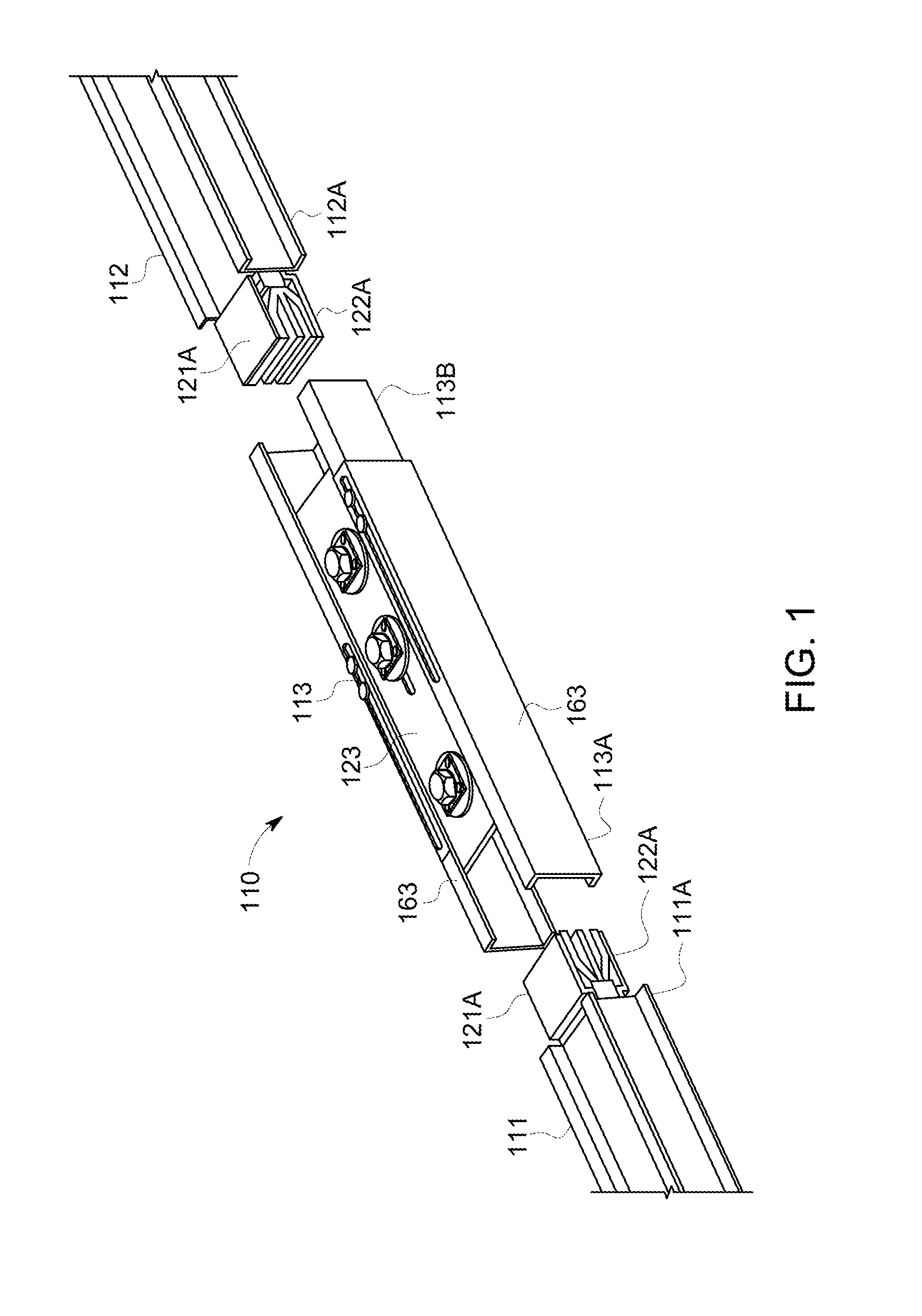
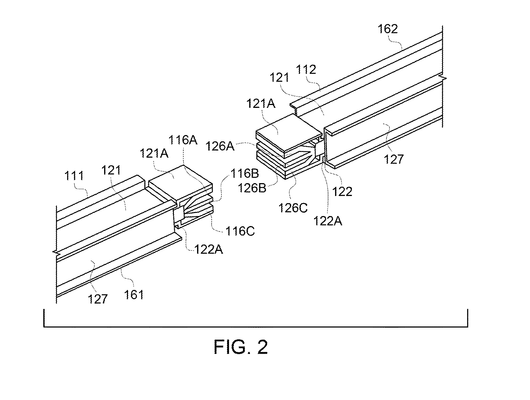
[0028]Various embodiments disclosed herein provide adjustable busway joints for busway systems. As used herein, a “busway joint” refers to a portion of a busway system (e.g., a joint, section, fitting, etc.) that is selectively extended and collapsed to fit between two or more portions of the busway system. For example, the busway joint may be coupled between two sections of the busway system. In another example, the busway joint may be coupled between a joint such as an elbow joint and a section of the busway system. The busway joints are installed and secured in place to prevent the busway joint from moving. The embodiments also describe techniques for securing internal ...


PUM


Abstract

A busway system is provided. The system includes a first electrical busway section, a second electrical busway section longitudinally offset from the first electrical busway section, and a busway joint coupling the first and second electrical busway sections. The busway joint includes a plurality of splice plates. Each splice plate includes a longitudinal rib configured to transfer a compressive force through the busway joint.

Description

BACKGROUND[0001]The field of the invention relates generally to an electrical busway, and, more particularly, to a variable length busway joint with forked busbars joining electrical busway sections.[0002]Elongated rectangular flat conductive busbar members are conventionally insulatively arranged within electrical busway sections for transporting multi-phase high current electric power through industrial, commercial, and / or residential establishments. Successive elongated busway sections are electrically connected or interlocked together in end-to-end relation to provide electrical continuity between a power source and a power consuming load.[0003]When longitudinally aligned busway sections are electrically interconnected in a conventional installation, a self-contained busway joint is typically employed. To preserve the thermal properties of the individual busway sections, the busway joint is conventionally constructed with electrically conductive splice plates and interleaving in...

Claims


Application Information

Patent Timeline
Patent Type & Authority Patents(United States)
IPC IPC(8): H01R4/60H02G5/00H01R25/14
CPCH01R25/145H02G5/007H01R25/167H02G5/005
Inventor MAURER, WILLIAM PATRICKNGUYEN, VU DINHGIFFORD, DENIZ SEMIH
Owner ABB (SCHWEIZ) AG
Why Eureka
Try Eureka