Heat exchange system
a heat exchange system and heat exchange technology, applied in indirect heat exchangers, lighting and heating apparatus, transportation and packaging, etc., can solve the problems of large space needed, large heat loss, and large difference in the amount of heat caused in the cooling circuit of a vehicle, so as to reduce the size reduce the temperature difference, and reduce the total heat exchange efficiency of the heat exchanger with respect to the air
- Summary
- Abstract
- Description
- Claims
- Application Information
AI Technical Summary
Benefits of technology
Problems solved by technology
Method used
Image

Examples
first embodiment
Modification of First Embodiment
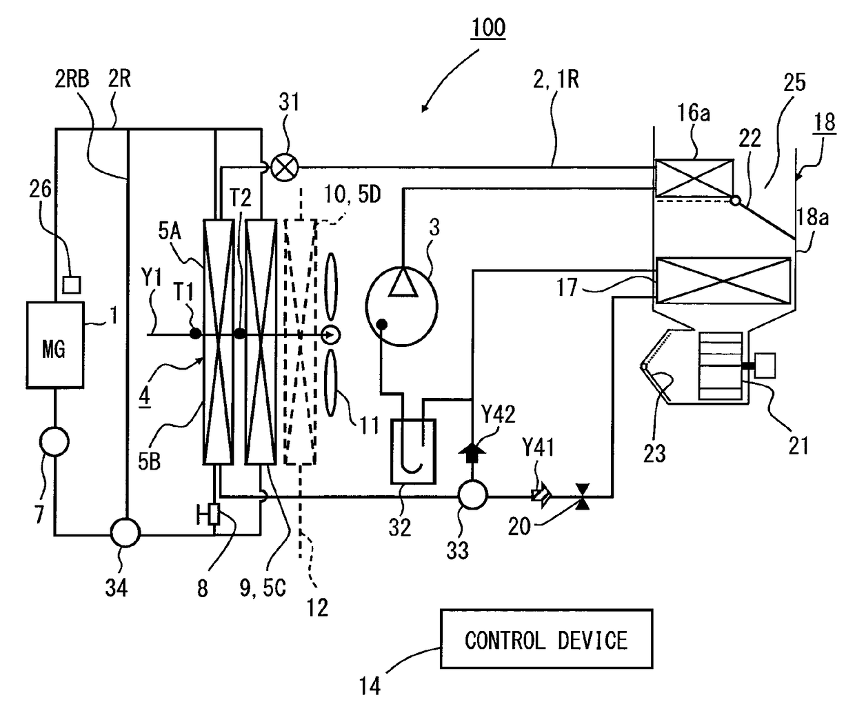
[0104]In the first embodiment, the tubes of the condenser 5A and the tubes of the heat exchanger 5B are alternately disposed so as to be substantially uniformly cooled by the flow of air. However, since the three-fluid heat exchanger 4 is produced with a two-row core, a relationship between the heat exchanger 5B, which is a part of the low-temperature heat exchangers disposed in the three-fluid heat exchanger 4, and the condenser 5A can be freely designed. For example, the heat exchanger 5B may be disposed on the upstream side in the flow of air and the condenser 5A may be disposed on the downstream side in the flow of air. Of course, on the contrary, the condenser 5A may be disposed on the upstream side in the flow of air and the heat exchanger 5B may be disposed on the downstream side in the flow of air.
[0105]Further, the flow control valve 8 may be electrically controlled by a signal transmitted from the control device 14 through a wire (not shown)...
second embodiment
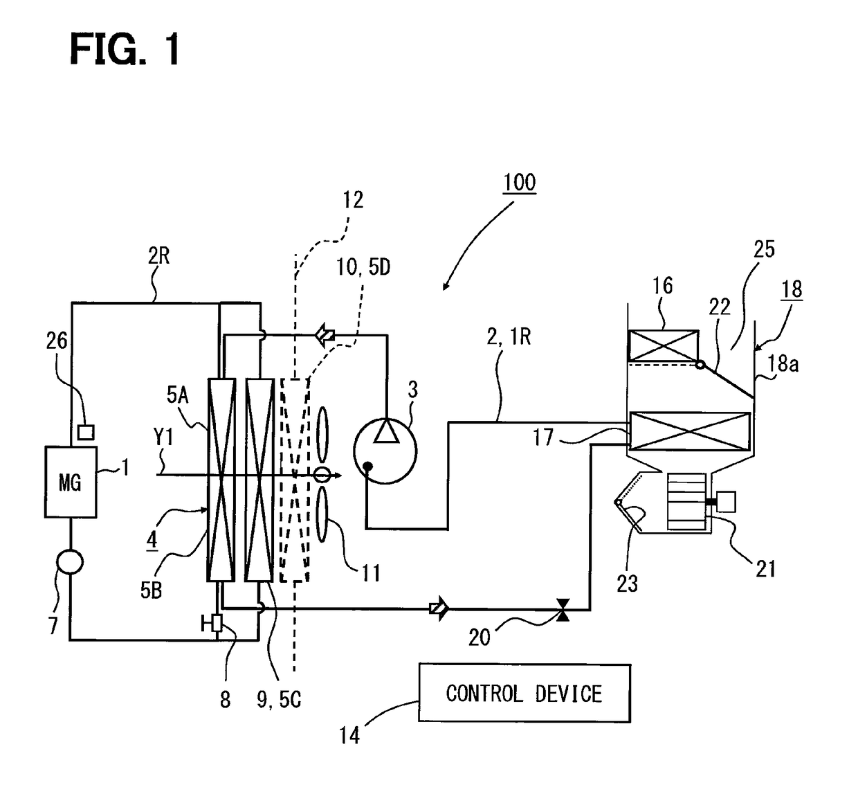
[0134]Next, a second embodiment of this disclosure will be described with reference to FIG. 3. In the following embodiments, the same elements as those of the above-mentioned first embodiment are denoted by the same reference numerals and the detailed description thereof will be omitted and other structures and features will be described. Further, the same reference numerals as the reference numerals of the first embodiment denote the same structures in the second embodiment and other embodiments, and preceding description will be applied to the same structures. FIG. 3 is different from FIG. 1 in that the second heat exchanger 5B and the third heat exchanger 5C are connected in series or parallel to each other, and the coolant for the motor generator MG flows in parallel in FIG. 1 and flows in series in FIG. 3.
[0135]FIG. 3 is an operational diagram of a cooling circuit illustrating a second embodiment of this disclosure. In FIG. 3, a refrigerating cycle 2 forms a cooling circuit by ...
third embodiment
[0140]Next, a third embodiment of this disclosure will be described with reference to FIG. 4. Features different from those of the above-mentioned embodiments will be described. FIG. 4 is different from FIG. 1 in that a liquid-cool condenser 30 and a brine pump 30a are disposed between a compressor 3 and a three-fluid heat exchanger 4 to form a circuit of an independent coolant (which is called brine in this disclosure) that relays the transfer of heat. While a coolant (LLC) and a refrigerant are used as fluid flowing in the three-fluid heat exchanger 4 in the case of FIG. 1, fluid flowing in the three-fluid heat exchanger 4 can be unified by a coolant (LLC) in the case of FIG. 4. Accordingly, the design and manufacture (including examination) of the three-fluid heat exchanger 4 are facilitated. That is, different countermeasures against pressure or corrosion are required for the refrigerant and the coolant, but manufacture and the like are facilitated when the same coolant is used ...
PUM
 Abstract
Description
Claims
Application Information
 - R&D Engineer
- R&D Manager
- IP Professional
- Industry Leading Data Capabilities
- Powerful AI technology
- Patent DNA Extraction
Browse by: Latest US Patents, China's latest patents, Technical Efficacy Thesaurus, Application Domain, Technology Topic.
© 2024 PatSnap. All rights reserved.Legal|Privacy policy|Modern Slavery Act Transparency Statement|Sitemap