Crank circular sliding block mechanism and reciprocating member, cylinder block, internal combustion engine, and compressor

a circular sliding block and reciprocating mechanism technology, applied in the direction of reciprocating piston engines, machines/engines, positive displacement engines, etc., can solve the problems of large space occupation, poor balance performance large volume of crank and connecting rod mechanisms, etc., to achieve the effect of improving the space arrangement of the crank circular sliding block mechanism and reducing the space occupation

Active Publication Date: 2017-03-14
BEIJING SINOCEP ENGINE TECH
View PDF17 Cites 3 Cited by
  • Summary
  • Abstract
  • Description
  • Claims
  • Application Information

AI Technical Summary

Benefits of technology

[0009]The invention provides a crank circular slider mechanism which can improve space arrangement of the crank circular slider mechanism so as to make it for the whole mechanism possible to realize a complete balance in a smaller space.
[0028]The invention provides a crank circular slider mechanism in which the reciprocating motion part comprises a multi-row reciprocating motion part and a one-row reciprocating motion part; the multi-row reciprocating motion part has a guiding part which is divided by a longitudinal groove into two parallel rows which are respectively called as a first row of guiding part and a second row of guiding part; the first row of guiding part is provided with a first circular slider receiving hole, the second row of guiding part is provided with a second circular slider receiving hole. The one-row of reciprocating motion part has a guiding part capable of being inserted into the longitudinal groove of the multi-row reciprocating motion part along the thickness and crosses vertically the multi-row of reciprocating motion part. The guiding part is provided with a middle circular slider receiving hole; the first circular slider and the second circular slider are mounted on the same phase. The middle circular slider is sandwiched between the first circular slider and the second circular slider and is located with a phase difference of 180 degree compared to the two circular sliders. The adjacent circular sliders are secured to each other. Provided that the center axis of the multi-row reciprocating motion part and the rotary axis of the crankshaft are crossed at point A and the center axis of the one-row reciprocating motion part and the rotary axis of the crankshaft are crossed at point B, the above mentioned structure can reduce the distance between points A and B notably and decreases the bending moment on the axis of the crankshaft due to the distance.
[0029]In the preferable solution of the crank circular slider mechanism, the multi-row reciprocating motion part has a first and second row of guiding parts which have same thickness and completely same structure. The said structure makes overlap of the points A and B possible and causes the bending moment along the axis of the crankshaft nonexistent and therefore improves the balance of the whole structure notably.

Problems solved by technology

Due to the presence of link rods in the crank and connecting rod mechanism, the crank and connecting rod mechanism internal combustion engines are bulky, heavy, and of poor balance performance.
The problems in the mechanism lie in that the distance L between the piston and the dynamic balance slider along the axis of the crankshaft exists so that they form a bent moment on the crankshaft so that the whole mechanism cannot balance completely.
However the better balance effect so relies on the middle reciprocating motion part, which makes the whole mechanism too complicated.
The machine requiring a small size will not possibly utilize the above mentioned mechanism.

Method used


Image

  • Crank circular sliding block mechanism and reciprocating member, cylinder block, internal combustion engine, and compressor
  • Crank circular sliding block mechanism and reciprocating member, cylinder block, internal combustion engine, and compressor
  • Crank circular sliding block mechanism and reciprocating member, cylinder block, internal combustion engine, and compressor

Examples


first embodiment

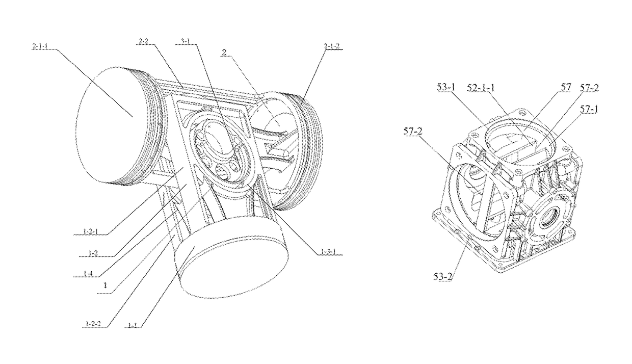
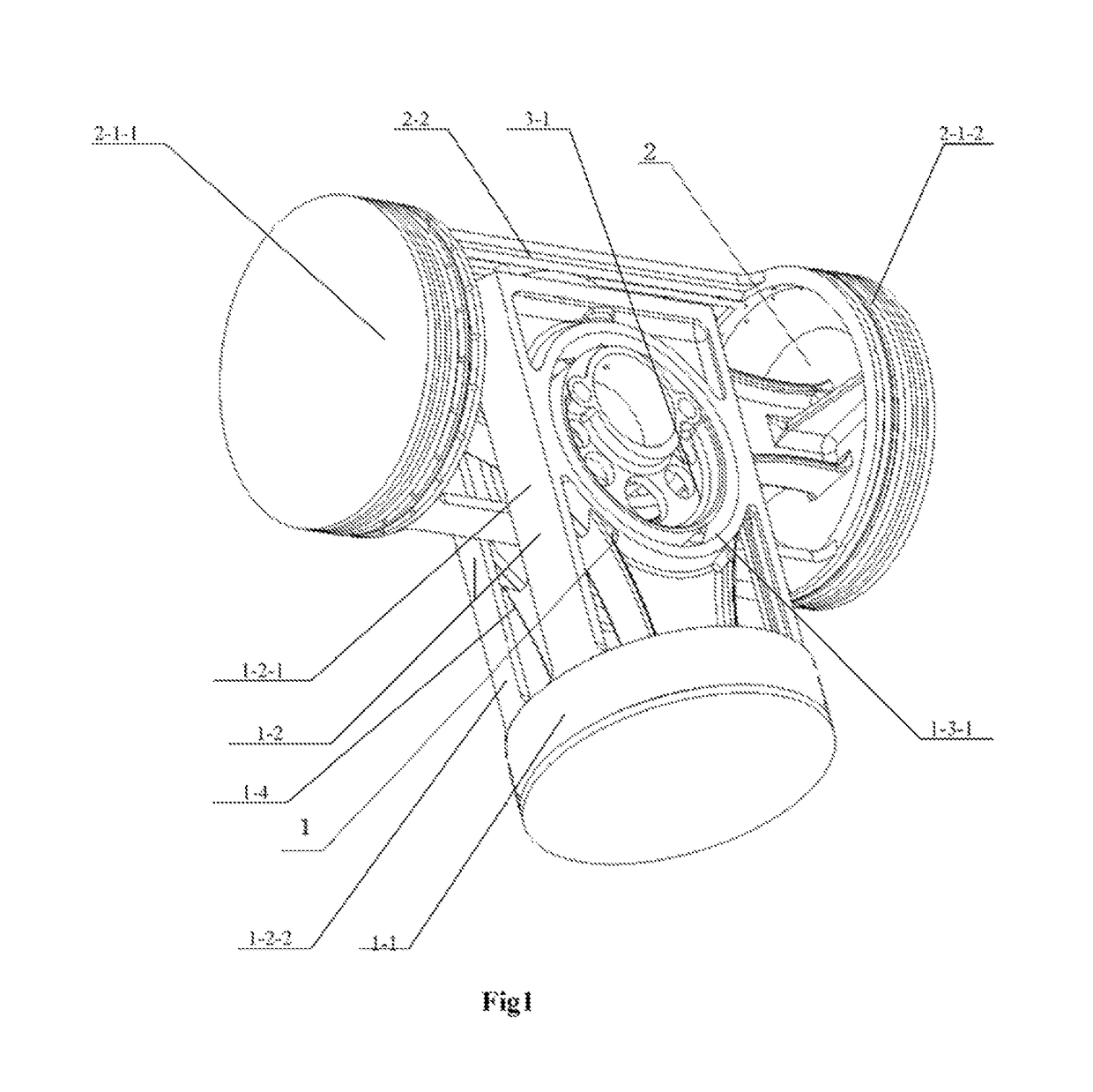
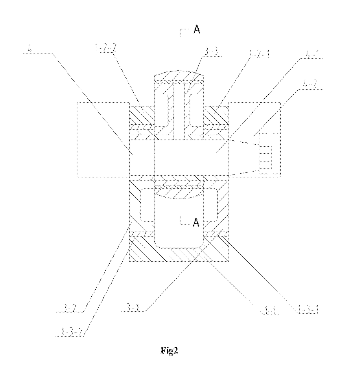
[0055]Please refer to FIG. 1, which is the schematic perspective of the I type crank circular slider mechanism proposed in the invention. In order to highlight the main features of the invention, the crankshaft of the crank circular slider mechanism is omitted in the view. Please also refer to FIG. 2, which is a plan cut view of the front face of the I type crank circular slider mechanism proposed in the embodiment. Please also refer to FIG. 3, which is a plan cut view of the I type crank circular slider mechanism proposed in the invention and is a left cut view of FIG. 2. Please also refer to FIG. 4 which is a front cut view of the dynamic balance slider 1.

[0056]As illustrated in the above figures, the I type crank circular slider mechanism comprises two reciprocating motion parts, respectively a dynamic balance slider 1 and a double action piston 2, which are placed respectively on the reciprocating motion tracks vertical to each other. The dynamic balance slider 1 moves up and do...

second embodiment

[0066]the invention provides a V type crank circular slider mechanism formed by a combination of the one single action multi-row piston and the one single action one row piston.

[0067]Please refer to FIG. 5, which is a perspective of V type crank circular slider mechanism in the second embodiment of the invention. In order to underline the features of the invention, the crankshaft is not shown in the perspective. As illustrated in FIG. 6, a partial cut view at the V type intersection (not showing the guiding part of the multi-row piston positioned in the outside) shows the second embodiment of the invention providing a V type crank circular slider mechanism. Please also refer to FIG. 7, which is a right view of A-A cut view of FIG. 6. Please also refer to FIG. 8 which is a cut front view of the multi-row piston 21.

[0068]As illustrated in the above figures, the V type crank circular slider mechanism comprises two reciprocating motion elements, respectively, a multi-row piston 21 and a...

third embodiment

[0077]the invention provides a crank circular slider mechanism for the single cylinder machine which is formed by the combination of the single action one row piston and the single crown and multi-row dynamic balance slider.

[0078]Please refer to FIG. 9, which is a perspective of the single cylinder mechanism of the crank circular slider provided by the third embodiment of the invention. In order to underline the features of the invention, the perspective does not show the crankshaft. Actually, the mechanism is required to be completely installed into the respective engine block so as to work. The mechanism may be utilized in the single cylinder internal combustion engine or the single cylinder compressor. Please refer to FIG. 10, which is a front cut view seen from one end of the crankshaft showing the single cylinder mechanism of the crank circular slider. Please refer to FIG. 11, which is bottom cut view of the embodiment. Please refer to FIG. 12, which is a front cut view of the ...


PUM


Abstract

A crank circular slider mechanism that includes a multi-row reciprocating motion part and a one-row reciprocating part. The multi-row reciprocating motion part has a guiding part divided by a longitudinal groove into two rows parallel to each other, each of which has a hole for a circular slider. The one-row reciprocating motion part has a guiding part which can be inserted into the longitudinal groove of the multi-row reciprocating motion part along the thickness direction, so as to vertically traverse the multi-row reciprocating motion part. The guiding part of the one-row reciprocating motion part includes a hole receiving a middle circular slider. Two circular sliders are mounted in the same phase; the middle circular slider is sandwiched therebetween and is located with a 180 degree phase difference compared to them. Adjacent circular sliders are secured to each other.

Description

PRIOR RELATED APPLICATIONS[0001]This application is a National Phase application of International Application No. PCT / CN2011 / 002038 filed Dec. 6, 2011, which claims priority to Chinese Patent Application No. 201010581951.4 filed Dec. 6, 2010, Chinese Patent Application No. 201010581937.4 filed Dec. 6, 2010, Chinese Patent Application No. 201010581946.3 filed Dec. 6, 2010, Chinese Patent Application No. 201010581950.X filed Dec. 6, 2010, Chinese Patent Application No. 201010581948.2 filed Dec. 6, 2010, Chinese Patent Application No. 201120238986.8 filed Jul. 7, 2011, and Chinese Patent Application No. 201110189964.1 filed Jul. 7, 2011, each of which is incorporated herein by reference in its entirety.TECHNICAL FIELD[0002]The invention relates to a reciprocating-rotary motion and inter-exchangeable mechanism, in particular, a crank circular-slider mechanism. The invention also provides a part designed for the crank circular slider mechanism. The invention also provides an equipment us...

Claims


Application Information

Patent Timeline
Patent Type & Authority Patents(United States)
IPC IPC(8): F01B1/06F01B9/02F02B75/32F02B75/18
CPCF01B1/06F01B9/026F02B75/32F02B2075/1812
Inventor LI, MINGLI, ZHENGZHONGMA, YUSHENGWANG, QINGXUGUO, LIJUN
Owner BEIJING SINOCEP ENGINE TECH
Why Eureka
Try Eureka