Method of diagnosing injector variability in a multiple injector system

a fuel injection system and injector variability technology, applied in the direction of machines/engines, electrical control, output power, etc., can solve the problems of piece-to-piece injector variability, deformation of injector performance, so as to achieve accurate pressure drop determination and precise adjustment

Active Publication Date: 2017-03-14
FORD GLOBAL TECH LLC
View PDF13 Cites 43 Cited by
  • Summary
  • Abstract
  • Description
  • Claims
  • Application Information

AI Technical Summary

Benefits of technology

[0006]In this way, injector degradation, and consequently, injector variability, can be learned by measuring fuel rail pressure drops and adjusting these for a closing delay of an injector. In an engine with multiple injectors per cylinder, a single injector can be isolated for calibration by fueling all but one cylinder with a first fuel and injecting a second fuel into the single cylinder via the injector being calibrated. During the calibration, pressure drops, along with closing delays, associated with each injection event may be measured. By correcting for an increase in closing delay, a more accurate determination of pressure drop can be made, particularly when the overall pressure decline in the fuel rail is significant. As such, this corrected pressure drop will lead to a more precise adjustment in an amount of fuel delivered by the injector.

Problems solved by technology

Fuel injectors often have piece-to-piece and time-to-time variability, due to imperfect manufacturing processes and / or injector aging, for example.
Over time, injector performance may degrade (e.g., injector becomes clogged) which may further increase piece-to-piece injector variability.
As a result, the actual amount of fuel injected to each cylinder of an engine may not be the desired amount and the difference between the actual and desired amounts may vary between injectors.
Such discrepancies can lead to reduced fuel economy, increased tailpipe emissions, and an overall decrease in engine efficiency.
Further, engines operating with a dual injector system, such as dual fuel or PFI / DI systems, may have even more fuel injectors (e.g., twice as many) resulting in a greater possibility for degradation of engine performance due to injector degradation.
For example, pumping of a second fuel into the second fuel rail is suspended while a first fuel is injected to all but a single cylinder of the engine, and, while pumping is suspended in the second fuel rail, the second fuel is injected into the single cylinder and corresponding pressure decrease in the second fuel rail is correlated to injector operation and possible degradation.
This decline in rail pressure may reduce injector backpressure causing an increase in injector closing delay and substantially affecting the accuracy of measured pressure drop.
Further, if the calibration event occurs over a longer period of time, a larger overall drop in fuel rail pressure with a corresponding large increase in injector closing delay may affect the accuracy of pressure drop measurements substantially.
Since measured pressure drops are correlated with an expected decrease to predict the presence (or absence) of injector degradation, inaccurate measurements can lead to incorrect conclusions about injector malfunction and subsequent fueling adjustments.

Method used


Image

  • Method of diagnosing injector variability in a multiple injector system
  • Method of diagnosing injector variability in a multiple injector system
  • Method of diagnosing injector variability in a multiple injector system

Examples


Embodiment Construction

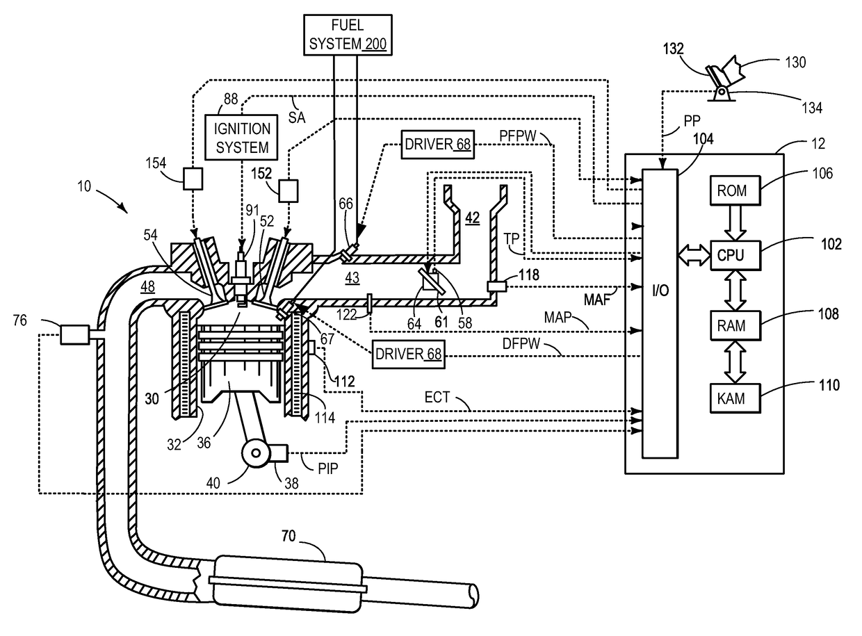
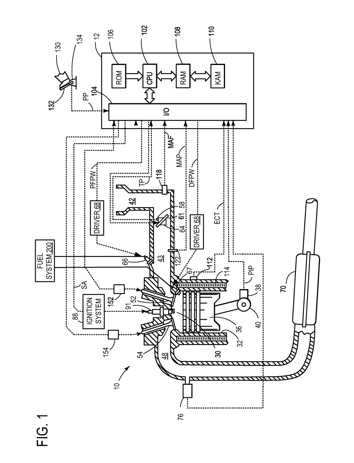
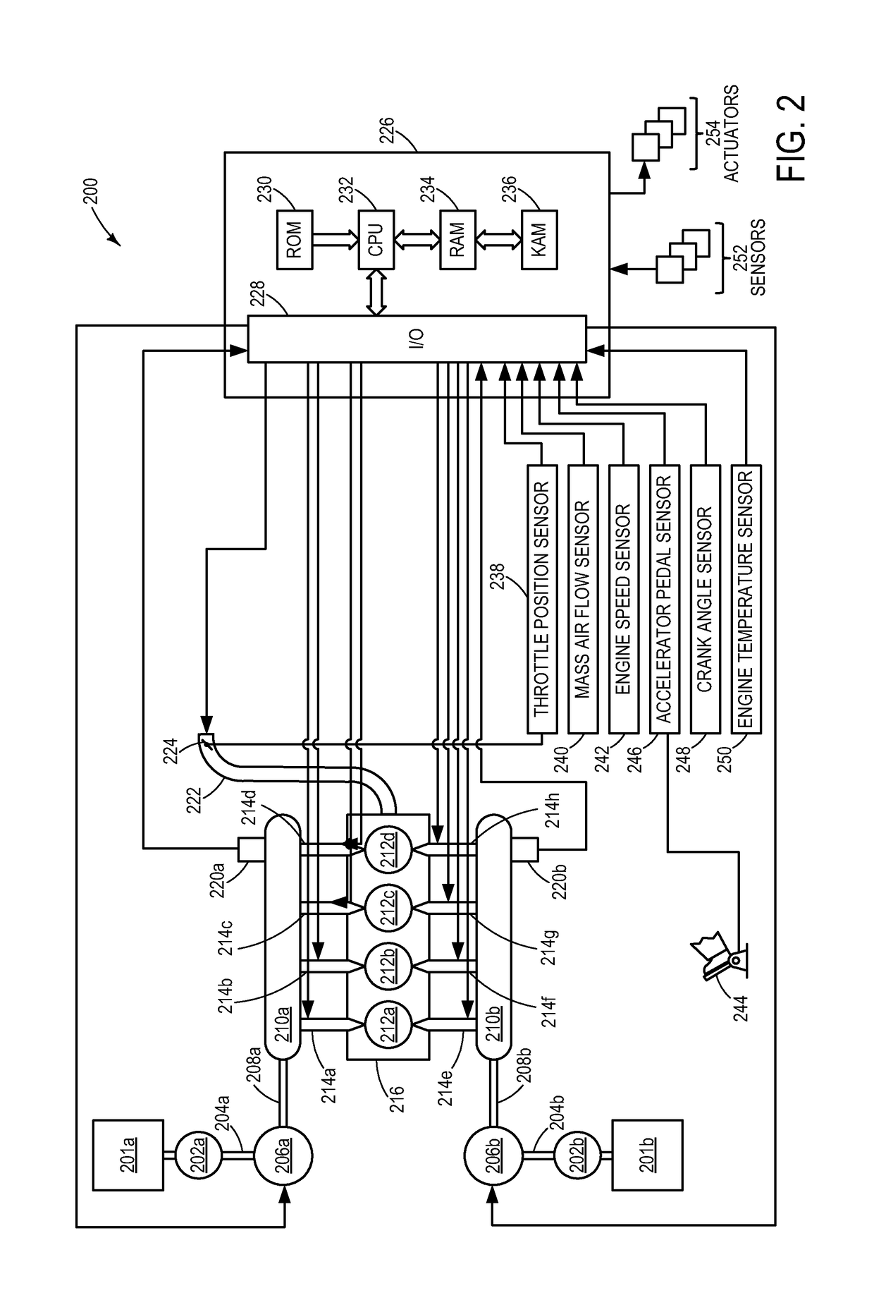
[0016]The following description relates to a method for controlling fuel injection in a multi-injector, multi-substance engine, such as a dual fuel engine, which includes first and second fuel rails and first and second fuel pumps as shown in FIG. 2. An example fuel system with two fuel injectors per cylinder, for at least one cylinder of a multi-cylinder engine is portrayed in FIG. 1. The two injectors may be configured in various locations, such as two port injectors, one port injector and one direct injector (as shown in FIG. 1), or others. A controller may be configured to perform a routine, such as the example routines of FIGS. 3-5, to confirm the need for an injector calibration, diagnose a fuel injector and correct a measured pressure drop. Examples of fuel injection timing and corresponding drops in fuel rail pressure are illustrated in FIGS. 6A and 6B. FIG. 7 portrays the relationship between injection slope and injection pressure while FIG. 8 illustrates the importance of ...


PUM


Abstract

Various systems and methods are described for diagnosing injector variability in a dual fuel, multi-injector system. In one example, a single injector in one cylinder is enabled while remaining cylinders are fueled with a first fuel and subsequently, a second fuel is injected via the enabled injector into the one cylinder in a predetermined sequence and fuel rail pressure drops are measured. Further, measured pressure drop after each injection event is corrected for an increase in injector closing delay.

Description

TECHNICAL FIELD[0001]The present application relates to diagnosing injector variability in a fuel injection system in a dual fuel engine.BACKGROUND AND SUMMARY[0002]Fuel injectors often have piece-to-piece and time-to-time variability, due to imperfect manufacturing processes and / or injector aging, for example. Over time, injector performance may degrade (e.g., injector becomes clogged) which may further increase piece-to-piece injector variability. As a result, the actual amount of fuel injected to each cylinder of an engine may not be the desired amount and the difference between the actual and desired amounts may vary between injectors. Such discrepancies can lead to reduced fuel economy, increased tailpipe emissions, and an overall decrease in engine efficiency. Further, engines operating with a dual injector system, such as dual fuel or PFI / DI systems, may have even more fuel injectors (e.g., twice as many) resulting in a greater possibility for degradation of engine performanc...

Claims


Application Information

Patent Timeline
Patent Type & Authority Patents(United States)
IPC IPC(8): F02D41/30F02D41/22F02D41/00F02D41/24F02D19/06F02D41/38F02D13/02
CPCF02D41/3094F02D19/061F02D19/0623F02D19/0628F02D19/0692F02D41/008F02D41/0025F02D41/221F02D41/2467F02D41/3076F02D13/0207F02D13/0219F02D41/3845F02D2200/06F02D2200/0602F02D2200/0618Y02T10/36Y02T10/40Y02T10/30F02M65/00
Inventor SURNILLA, GOPICHANDRARANGA, ADITHYA PRAVARUN REMEINHART, MARK
Owner FORD GLOBAL TECH LLC
Why Eureka
Try Eureka