
Method of creating and closing a drywall temporary access opening

a technology of creating and closing a temporary access and a drywall board, which is applied in the field of creating and closing temporary access, can solve the problems of requiring additional materials and time, requiring additional materials, and existing methods that do not produce leveled joints and an even surface, and achieves the effect of simplifying the process of restoring and simplifying the creation of temporary access

Active Publication Date: 2017-03-21
CHAGIN YURIY +1
View PDF4 Cites 0 Cited by
  • Summary
  • Abstract
  • Description
  • Claims
  • Application Information

AI Technical Summary

Benefits of technology

[0006]The purpose of the tool is to simplify creation of temporary access to the area behind the drywall and to simplify the processes of restoring the drywall to its original condition after completion of the work.
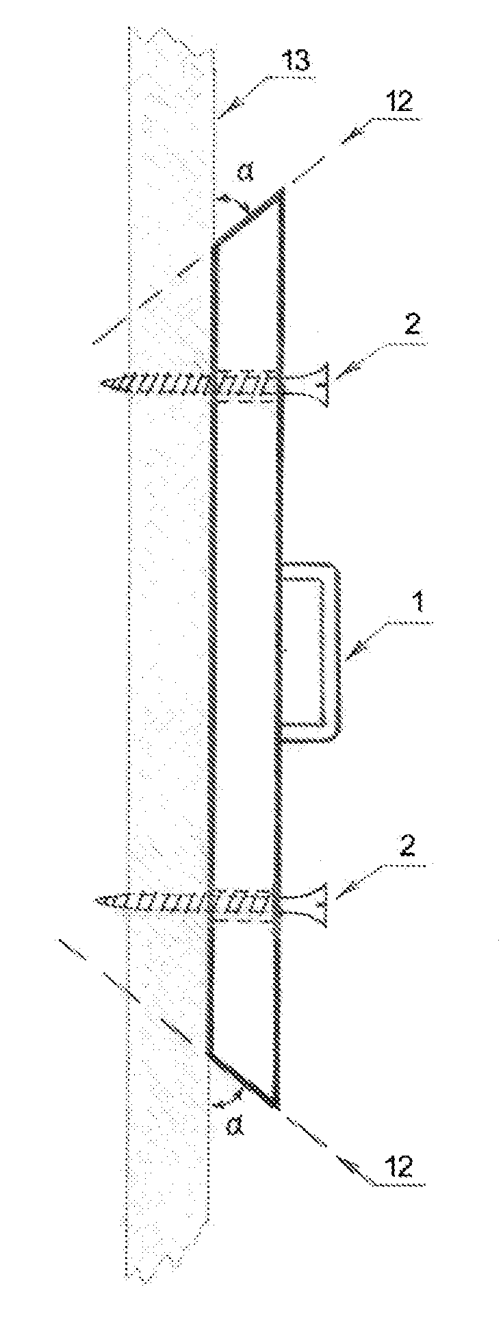
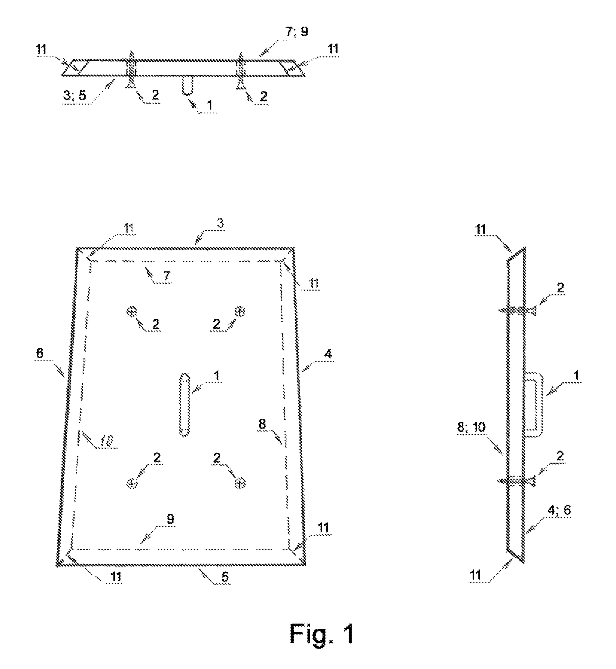
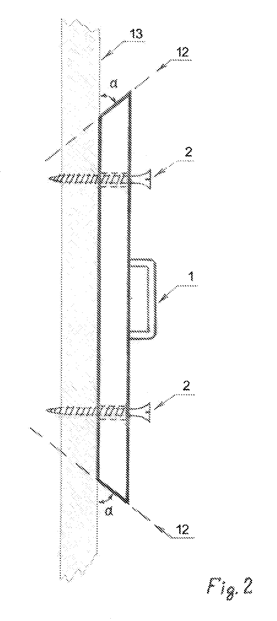
[0007]The simplicity of the process is achieved by cutting the drywall in a way, which will result in the inner perimeter of the temporary access opening to be smaller than the outer perimeter. The inner perimeter of the cutout drywall piece will also be smaller than the outer perimeter of the same piece. The cutout drywall piece will resemble a partial pyramid shape or a partial cone shape.
[0008]The smaller inner perimeter of the temporary access opening and the extracted drywall piece will eliminate the need for additional support to be placed behind the drywall when restoring the wall to original condition. The partial pyramid shape will prevent the extracted drywall piece from falling inside when inserted back to close the temporary access.

Problems solved by technology

Existing methods of creating and closing temporary access on drywall boards are primitive, they require additional materials and time.
Existing methods do not produce leveled joints and a smooth even surface when closing temporary access.
All these procedures consume a lot of time and materials as well as creating unhealthy conditions by exposing workers to more dust resulted from sanding each layer.

Method used


Image

  • Method of creating and closing a drywall temporary access opening
  • Method of creating and closing a drywall temporary access opening
  • Method of creating and closing a drywall temporary access opening

Examples


Embodiment Construction

[0027]The purpose of this tool is to simplify the process of creating and closing a temporary access in a drywall. The simplicity of the process is achieved by cutting the drywall in a way, which will result in the inner perimeter of the temporary access opening to be smaller than the outer perimeter. The inner perimeter of the cutout drywall piece will also be smaller than the outer perimeter of the same piece. The cutout drywall piece will resemble a partial pyramid shape or a partial cone shape. A partial pyramid shape or a partial cone shape of the extracted drywall piece will eliminate the need for additional support to be placed behind the drywall when restoring the wall to its original condition. The partial pyramid shape will prevent the extracted drywall piece from falling inside when inserted back to close the temporary access.

[0028]The tool could be implemented in a variety of flat shapes such as circle, oval and polygons comprising: triangle, square, trapezoid, rectangle...


PUM

PropertyMeasurementUnit
cutting anglesaaaaaaaaaa
perimeteraaaaaaaaaa
thicknessaaaaaaaaaa

Abstract

A method to create a temporary access opening in a drywall of a wall structure to access the area behind the wall structure to perform a type of work and to simplify the process of closing of the temporary access opening after completion of the work. A tool to simplify the creation of the temporary access opening is securely attached to the drywall permitting the drywall to be cut. A cutting tool will be used to cut the drywall along the sides of the tool at a certain angle and that angle will allow the cutout drywall piece to be reused to close the temporary access opening without using any supporting material otherwise required to be placed behind the wall to prevent the extracted piece from falling behind the wall structure during the closing step.

Description

BACKGROUND OF THE INVENTION[0001]Existing methods of creating and closing temporary access on drywall boards are primitive, they require additional materials and time. Existing methods of closing temporary access require additional support to be placed behind the drywall to prevent the cutout piece from falling inside. Existing methods do not produce leveled joints and a smooth even surface when closing temporary access. To achieve flat even surface skilled workers have to apply several layers of a joint compound and allow significant time for the joint compound to dry before applying each layer. Sanding might also be required before the application of each layer. All these procedures consume a lot of time and materials as well as creating unhealthy conditions by exposing workers to more dust resulted from sanding each layer. It might take up to several days for drywall to be restored to original condition.BRIEF SUMMARY OF THE INVENTION[0002]The drywall temporary access creation and...

Claims


Application Information

Patent Timeline
Patent Type & Authority Patents(United States)
IPC IPC(8): B26B29/06E04G23/02
CPCE04G23/0203B26B29/06Y10T29/49732
Inventor CHAGIN, YURIYCHAGIN, YELENA
Owner CHAGIN YURIY
Learn More