Bidirectional valved aspirator for surge control and vacuum generation

a technology of surge control and vacuum generation, which is applied in the direction of combustion-air/fuel-air treatment, machine/engine, fuel air intake, etc., can solve the problems of compressor degradation, incorporated valves, performance issues, etc., and achieve significant component and operating costs, prolong the operating region of the engine, and prevent objectionable audible noise

Active Publication Date: 2017-03-21
FORD GLOBAL TECH LLC
View PDF10 Cites 12 Cited by
  • Summary
  • Abstract
  • Description
  • Claims
  • Application Information

AI Technical Summary

Benefits of technology

[0002]Turbocharging an engine allows the engine to provide power similar to that of a larger displacement engine. Thus, turbocharging can extend the operating region of an engine. Turbochargers function by compressing intake air in a compressor via a turbine operated by exhaust gas flow. Under certain conditions, the flow rate and pressure ratio across the compressor can fluctuate to levels that may result in noise disturbances, and in more severe cases, performance issues and compressor degradation. Such compressor surge may be mitigated by one or more compressor bypass valves (CBVs). The CBVs may recirculate compressed air from the compressor outlet to the compressor inlet, and thus may be arranged in a passage which is coupled to the intake upstream of the compressor and downstream of the compressor in some examples. In some examples, continuous CBVs (CCBVs) may be used, which provide a continuous and continually variable circulation flow from downstream of the compressor to upstream of the compressor. CCBVs may provide boost control and compressor surge avoidance, and may further prevent objectionable audible noise. However, incorporation of such valves can add significant component and operating costs to engine systems.
[0004]While aspirators may generate vacuum at a lower cost and with improved efficiency as compared to electrically-driven or engine-driven vacuum pumps, it may be necessary to include an aspirator shut-off valve to regulate flow through the aspirator. By controlling the opening amount of the valve, the amount of air flowing through the aspirator and the air flow rate can be varied, thereby adjusting vacuum generation as engine operating conditions such as intake manifold pressure change. However, again, adding valves to engine systems can add significant component and operating costs. Further, while a door or gate of a typical aspirator shut-off valve may open easily during one direction of flow through the valve, flow in the opposite direction may exert force in a direction opposing the opening of the door or gate, which may negatively impact operation of the valve and / or increase the amount of energy required to open the valve.
[0005]Further, typically, aspirators are designed with a sonic / supersonic expansion curve in one direction and with a single entraining port to harness vacuum generated as the motive flow passes through the converging-diverging nozzle of the aspirator. To reduce manufacturing costs, the port may be created via injection molding, and may have sharp edges (e.g. edges perpendicular to a motive flow axis of the aspirator) due to the insertion of the injection molding tool which forms the port. Reverse flow through such an aspirator may not achieve the same sonic / supersonic expansion due to flow disruption caused by the sharp edges of the port, as well as due to the aspirator being designed for sonic / supersonic expansion for only one direction of flow.
[0006]To address at least some of the above issues, the inventors herein have recognized that an aspirator coupling an inlet of a compressor with an intake manifold may include a first entraining port coupling an ambient side of the aspirator with a vacuum source and a second entraining port coupling a manifold side of the aspirator with the vacuum source, and may be designed such that both of an expansion curve from an ambient side to a manifold side of the aspirator and an expansion curve from the manifold side to the ambient side of the aspirator are sonic / supersonic expansion curves. For example, the expansion curve from the manifold side to the ambient side of the aspirator may be tuned to mass flow densities near a typical boost condition of the engine. Accordingly, the aspirator may function as a vacuum-generating CBV during boost conditions, such that a dedicated CBV may be omitted from the engine system so as to advantageously reduce component and manufacturing costs. To minimize flow disruption which might otherwise result from the incorporation of an extra entraining port in the aspirator, the first entraining port may be counter sunk relative to a nominal slope of the aspirator, and a side of the first entraining port closer to a throat of the aspirator may be proud relative to a nominal slope of the aspirator.
[0007]Further, the inventors herein have recognized that bidirectional flow through the aspirator may be enhanced by the use of a radial-flow aspirator shut-off valve. Whereas motive flow may enter typical aspirator shut-off valves without diverging from a motive flow path through the aspirator (e.g., a door or gate of these valves may open such that motive flow may enter an opening which is coaxial with a motive flow axis of the aspirator), motive flow may enter a radial-flow shut-off valve in a direction perpendicular to a direction of motive flow through the aspirator. Accordingly, using a radial-flow shut-off valve may reduce energy consumption of the valve as well as flow disruption / backpressure which may occur when non-radial-flow aspirator shut-off valves are used.
[0008]Therefore, some of the technical results achieved by the engine systems and methods described herein include reduced manufacturing and component costs due to the omission of a dedicated CBV, reduced energy consumption due to the use of a radial-flow aspirator shut-off valve, and vacuum generation during boost and non-boost conditions.

Problems solved by technology

Under certain conditions, the flow rate and pressure ratio across the compressor can fluctuate to levels that may result in noise disturbances, and in more severe cases, performance issues and compressor degradation.
However, incorporation of such valves can add significant component and operating costs to engine systems.
However, again, adding valves to engine systems can add significant component and operating costs.
Further, while a door or gate of a typical aspirator shut-off valve may open easily during one direction of flow through the valve, flow in the opposite direction may exert force in a direction opposing the opening of the door or gate, which may negatively impact operation of the valve and / or increase the amount of energy required to open the valve.
Reverse flow through such an aspirator may not achieve the same sonic / supersonic expansion due to flow disruption caused by the sharp edges of the port, as well as due to the aspirator being designed for sonic / supersonic expansion for only one direction of flow.

Method used


Image

  • Bidirectional valved aspirator for surge control and vacuum generation
  • Bidirectional valved aspirator for surge control and vacuum generation
  • Bidirectional valved aspirator for surge control and vacuum generation

Examples


Embodiment Construction

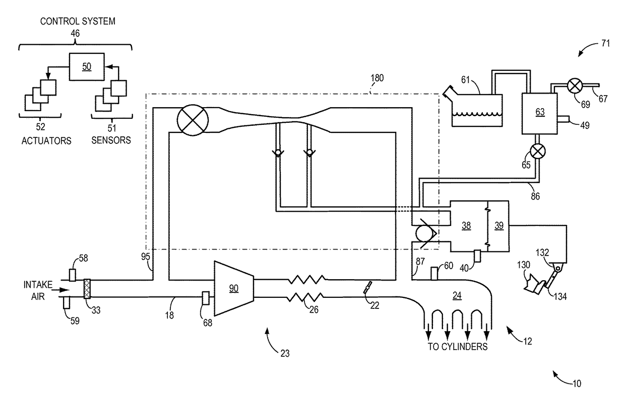
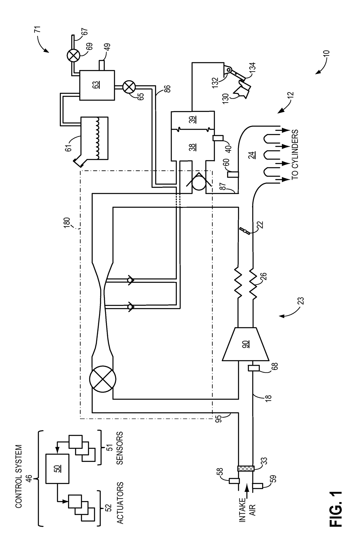
[0018]Methods and systems are provided for controlling a motive flow rate through a bidirectional valved aspirator bypassing a boost device arranged in an intake of an engine system such as the engine system depicted in FIG. 1. A detail view of an exemplary aspirator which may be included in the engine system of FIG. 1 is provided in FIG. 2, and a detail view of the aspirator of FIG. 2 during boost conditions and non-boost conditions is shown in FIGS. 3A and 3B, respectively. Depending on engine operating conditions, whether throttle fault conditions are present, and whether boost is active, various controls may be enacted to achieved a desired flow rate through a bidirectional valved aspirator (e.g., see the method of FIG. 4). For example, a desired motive flow rate through a bidirectional valved aspirator may be determined in accordance with the method of FIG. 5 during non-boost conditions, and in accordance with the method of FIG. 6 during boost conditions. The desired combined m...


PUM


Abstract

An aspirator coupled between an inlet of a compressor and an engine intake manifold may include sonic / supersonic expansion curves for both forward and reverse flow through the aspirator. Suction flow may enter a first entraining port coupling an ambient side of the aspirator with a vacuum source during reverse flow through the aspirator, whereas suction flow may enter a second entraining port coupling a manifold side of the aspirator with the vacuum source, the first entraining port counter sunk relative to a nominal slope of the aspirator to reduce flow disruption caused by the port during forward flow through the aspirator. A radial-flow aspirator shut-off valve arranged in series with the aspirator may be controlled to enable or disable motive flow through the aspirator, and motive flow may enter the valve in a direction perpendicular to a motive flow axis of the aspirator when the valve is open.

Description

FIELD[0001]The present application relates to a bidirectional valved aspirator bypassing an intake compressor in an engine system. In one example, a motive flow rate through the aspirator may be controlled via control of an aspirator shut-off valve to provide vacuum generation during non-boost conditions, and to provide compressor recirculation flow while generating vacuum during boost conditions.BACKGROUND AND SUMMARY[0002]Turbocharging an engine allows the engine to provide power similar to that of a larger displacement engine. Thus, turbocharging can extend the operating region of an engine. Turbochargers function by compressing intake air in a compressor via a turbine operated by exhaust gas flow. Under certain conditions, the flow rate and pressure ratio across the compressor can fluctuate to levels that may result in noise disturbances, and in more severe cases, performance issues and compressor degradation. Such compressor surge may be mitigated by one or more compressor bypa...

Claims


Application Information

Patent Timeline
Patent Type & Authority Patents(United States)
IPC IPC(8): F02B33/44F02B33/00F02M35/10
CPCF02M35/10118F02M35/10229F02M25/0836F02M25/0854F02M25/0872F02M35/10157F02M35/10222F02M35/10255F02M35/104Y02T10/12
Inventor LUEHRSEN, ERICPURSIFULL, ROSS DYKSTRA
Owner FORD GLOBAL TECH LLC
Why Eureka
Try Eureka