Polygon compensation coupling for chain and sprocket driven systems
a technology of sprocket and chain, which is applied in the direction of belt/chain/gearing, transportation and packaging, and transportation. it can solve the problems of reducing the lifespan of the components of the step chain sprocket, increasing the overall cost of the associated system, and reducing the polygon
- Summary
- Abstract
- Description
- Claims
- Application Information
AI Technical Summary
Benefits of technology
Problems solved by technology
Method used
Image
Examples
second embodiment
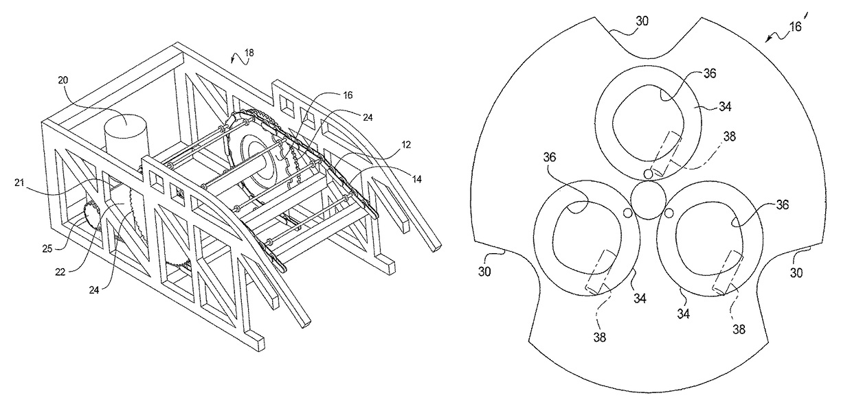
[0059]Referring now to FIG. 8, a schematic representation of the polygon compensation coupling system 28 is shown as 28′, in accordance with at least some embodiments of the present disclosure. To the extent that the polygon compensation coupling system 28′ is substantially similar to the polygon compensation coupling system 28, only the differences between the two will be described here, for conciseness of expression. As shown, similar to the polygon compensation coupling system 28, the polygon compensation coupling system 28′ may include the step chain 12 having the plurality of step chain links 14 and connecting links 32 that engage with the teeth 30 of the STC sprocket 16″ as the step chain moves about the rotating STC sprocket. The STC sprocket 16″ also has the three compensation holes 34, which define the compensation curve 42. In contrast to the polygon compensation coupling system 28 in which the MDC sprockets 24′ are shown to be circular (or substantially circular), the pol...
third embodiment
[0062]Turning now to FIGS. 9 and 10A-10B, the polygon compensation coupling system 28 is shown as 28″, in accordance with at least some embodiments of the present disclosure. In contrast to the polygon compensation coupling systems 28 and 28′, the polygon compensation coupling system 28″ employs a stationary plate 50 having a circumference that is defined by the determined compensation curve 42 above, as well as engagement surfaces (e.g., linear slots) 51 in the STC sprocket 16″′ and corresponding engagement surfaces (e.g., linear slots) 52 in the MDC sprockets 24″′ (only the linear slots in the MDC sprocket are visible in FIG. 9), all of which may be mounted to center around a common midpoint 54. The MDC sprocket 24″′ may be connected to the STC sprocket 16″′ by a way of a system fixation 56.
[0063]By virtue of the compensation curve 42 being fixed, it drives an engagement point 58 in a manner that the step chain 12 maintains a substantially constant linear speed when the MDC sprock...
PUM
 Abstract
Description
Claims
Application Information
 - R&D
- Intellectual Property
- Life Sciences
- Materials
- Tech Scout
- Unparalleled Data Quality
- Higher Quality Content
- 60% Fewer Hallucinations
Browse by: Latest US Patents, China's latest patents, Technical Efficacy Thesaurus, Application Domain, Technology Topic, Popular Technical Reports.
© 2025 PatSnap. All rights reserved.Legal|Privacy policy|Modern Slavery Act Transparency Statement|Sitemap|About US| Contact US: help@patsnap.com


