Correction of angle errors in permanent magnets

a permanent magnet and angle correction technology, applied in the field of magnet arrangement, can solve the problems of high cost, angle errors in the magnetization and/or orientation of the magnet material, etc., and achieve the effect of producing a magnet arrangemen

Active Publication Date: 2017-03-21
CONTINENTAL TEVES AG & CO OHG
View PDF18 Cites 0 Cited by
  • Summary
  • Abstract
  • Description
  • Claims
  • Application Information

AI Technical Summary

Benefits of technology

[0004]An aspect of invention is based on the problem of proposing a magnet arrangement and a method for producing a magnet arrangement which is relatively inexpensive and / or simple and / or enables a relatively high degree of precision of the magnetization and / or magnetizability with respect to a main magnetization direction and / or main direction of magnetizability of the entire magnet arrangement.
[0017]It is preferred that the magnet arrangement is designed in such a way that the two strong poles or the two weak poles of the two part-magnets or of adjacent or in each case all of the adjacent part-magnets join one another. As a result, in particular the north-south error of the magnet arrangement can be avoided or reduced or substantially corrected.
[0019]It is preferred that, with respect to this radial magnetization or radial magnetizability or this radial angle error, one part-magnet is arranged relative to the adjoining other part-magnet in such a way as to be rotated through an angle of between 140° and 220° or through an angle of between 170° and 190° or through an angle of substantially 180°, in particular rotated about the length or longitudinal axis of the part-magnet as axis of rotation. As a result, in particular an angle error or a radial angle error of the magnet arrangement can be avoided or reduced.

Problems solved by technology

Angle errors in the magnetization and / or orientation of the magnet material often occur during production of permanent magnets, in particular anisotropic permanent magnets.
Keeping these angle errors as small as possible or avoiding them is relatively complex and can result in relatively high costs, depending on the degree of desired prism of the magnetization direction or orientation of the magnet material.

Method used


Image

  • Correction of angle errors in permanent magnets
  • Correction of angle errors in permanent magnets
  • Correction of angle errors in permanent magnets

Examples


Embodiment Construction

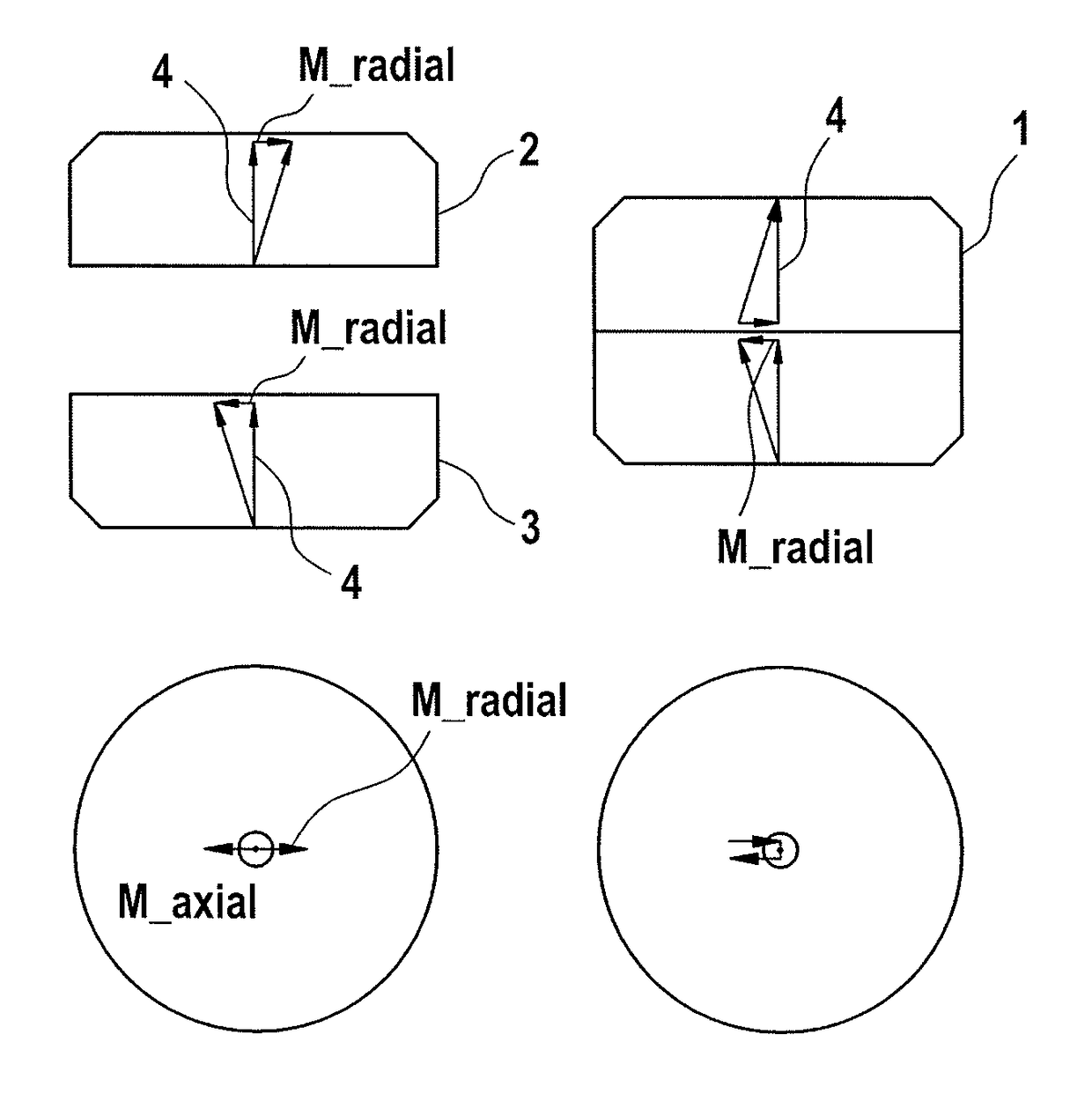
[0056]Many applications for measured value acquisition are implemented using magnetic sensors. For this purpose, the actual sensor and a permanent magnet are used. The sensor detects the magnetic field emanating from the magnet, for example by means of a Hall effect sensor, the direction of the magnetic field, for example by means of an AMR sensor, or uses the magnetizing effect thereof, for example by means of a flux-gate sensor or an inductively acting sensor. Often, rotationally symmetric magnetic fields are required which are generated by permanent magnets in the form of round plates or rings or cylinders. These rings or round plates or cylinders are magnetized axially thereto, i.e. in their longitudinal direction. It is desirable or necessary for the mechanical and the magnetic axis of symmetry or longitudinal or main direction to be congruent or aligned. Unfortunately, it is often not possible for manufacturing-related reasons for the magnetic and mechanical axis of symmetry t...


PUM

PropertyMeasurementUnit
angleaaaaaaaaaa
angleaaaaaaaaaa
angleaaaaaaaaaa

Abstract

At least two partial magnets mechanically connected to each other. The length of each partial magnet runs in the main magnetisation direction of each partial magnet and / or in the main direction in which a partial magnet can be magnetised or in which its magnetisation is intended, and defines a first side and a second side as opposed regions at the ends of the partial magnet in respect of its length The at least two partial magnets are arranged in sequence in respect of their lengths and connected to each other. Deviations in the direction of the magnetisation and / or magnetisability of the first partial magnet deviating from the main magnetisation direction and / or main direction of magnetisability reduce and / or substantially compensate for the deviations in the direction of the magnetisation and / or magnetisability of the other or of the adjacent partial magnet deviating from the main magnetisation direction and / or main direction of magnetisability.

Description

CROSS REFERENCE TO RELATED APPLICATIONS[0001]This application is the U.S. National Phase Application of PCT International Application No. PCT / EP2013 / 075956, filed Dec. 9, 2013, which claims priority to German Patent Application No. DE 10 2012 023 897.5, filed Dec. 7, 2012, the contents of such applications being incorporated by reference.FIELD OF THE INVENTION[0002]The invention relates to a magnet arrangement and to a method for producing a magnet arrangement.BACKGROUND OF THE INVENTION[0003]Angle errors in the magnetization and / or orientation of the magnet material often occur during production of permanent magnets, in particular anisotropic permanent magnets. Keeping these angle errors as small as possible or avoiding them is relatively complex and can result in relatively high costs, depending on the degree of desired prism of the magnetization direction or orientation of the magnet material.SUMMARY OF THE INVENTION[0004]An aspect of invention is based on the problem of proposin...

Claims


Application Information

Patent Timeline
Patent Type & Authority Patents(United States)
IPC IPC(8): H01F7/02H01F41/02H01F13/00B22F3/02B22F3/10B22F3/12
CPCH01F7/0278B22F3/02B22F3/10B22F3/12H01F7/021H01F13/003H01F41/0266Y10T29/49828
Inventor GRUNWALD, FRANK
Owner CONTINENTAL TEVES AG & CO OHG
Why Eureka
Try Eureka