Catheter pump arrangement and flexible shaft arrangement having a core

a flexible shaft and catheter pump technology, applied in the field of mechanical engineering, can solve the problem of not being able to achieve small bending radii in the portions with a cor

Active Publication Date: 2017-03-28
ECP ENTWICKLUNGSGMBH
View PDF259 Cites 27 Cited by
  • Summary
  • Abstract
  • Description
  • Claims
  • Application Information

AI Technical Summary

Benefits of technology

[0009]It is the underlying object of the present invention against the background of the prior art to provide a heart catheter pump arrangement having a shaft arrangement as well as a flexible shaft arrangement with the least possible construction means, said shaft arrangement providing resistance to a mechanical build-up of vibrations and knocking of the shaft and also corresponding noise development.

Problems solved by technology

The flexibility of the shaft arrangement in the sections reinforced by the core is smaller than in the sections not reinforced by the core and, accordingly, on a bending load, no small bending radii can be achieved in the portions with a core.

Method used


Image

  • Catheter pump arrangement and flexible shaft arrangement having a core
  • Catheter pump arrangement and flexible shaft arrangement having a core
  • Catheter pump arrangement and flexible shaft arrangement having a core

Examples


Embodiment Construction

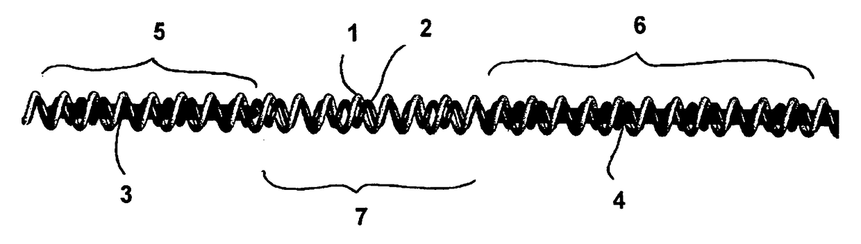
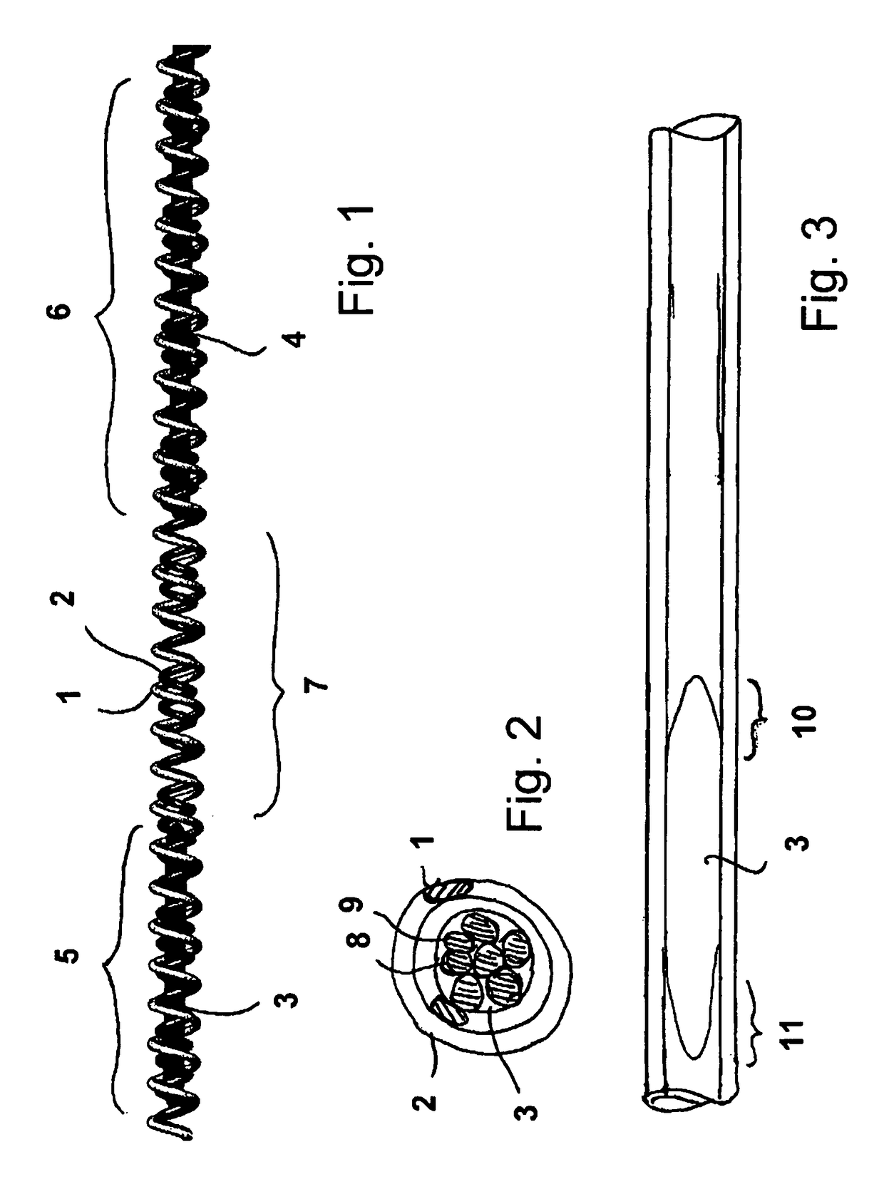
[0043]FIG. 1 shows, in a three-dimensional view, a hollow shaft which comprises two helical screws 1, 2 which are wound in opposite senses and of which the first is shown as light and the second as dark. The winding in opposite senses of the two helical springs has the effect that one of the springs is compressed and the other is stretched in each direction of rotation. There is thus no deformation overall in the axial direction in dependence on the direction of rotation which is to be transferred.

[0044]The density of the windings of the individual springs and the thickness of the spring wire determine, on the one hand, the flexibility or stiffness respectively of the hollow shaft and, on the other hand, the torque which can be transferred.

[0045]Two core sections 3, 4 are furthermore shown in FIG. 1 which each stiffen the shaft arrangement in the axial sections 5, 6. The hollow shaft remains free in the axial section lying therebetween and is correspondingly more flexible there.

[004...


PUM


Abstract

The invention relates to a flexible shaft arrangement having a flexible hollow shaft which has an end at the drive side and an end at the output side, wherein the hollow shaft is reinforced sectionally between these ends by a core extending in its interior. Stiffer and more flexible sections can hereby be selectively positioned within the shaft arrangement.

Description

BACKGROUND OF THE INVENTION[0001]The invention is in the field of mechanical engineering and specifically relates to the transfer of movements and of torques via flexible shafts.[0002]Flexible shafts of this type allow the transfer of torques for certain applications, for example to points which are difficult to access, e.g. for do-it-yourself (DIY) machinery or for dental applications where machining tools have to be introduced into the mouth of a patient. Small flexible shafts are generally suitable for use in the medical area, for example also for the drive of micropumps such as heart catheter pumps which are introduced into a body for the conveying of the body's own fluids, or for use in micromillers which can be used for removing tissue or deposits.[0003]Various problems are known in the operation of such flexible shafts, in particular at high speeds, with one of these problems comprising the fact that a high noise development can arise due to imbalance or other mechanical irre...

Claims


Application Information

Patent Timeline
Patent Type & Authority Patents(United States)
IPC IPC(8): A61M1/10A61M1/12F16C1/00A61M60/135A61M60/216A61M60/408A61M60/857
CPCA61M1/101A61M1/1034A61M1/125F16C1/00A61M60/414A61M60/135A61M60/148A61M60/408A61M60/857A61M60/216F16C1/02F16C1/26
Inventor ROEHN, DANIELLIEBING, REINER
Owner ECP ENTWICKLUNGSGMBH
Why Eureka
Try Eureka