
Multi-column tension leg platform

a leg platform and multi-column technology, applied in vessel construction, special-purpose vessels, transportation and packaging, etc., can solve the problems of not being able to handle subsidence well, requiring more complex and expensive fixed platform designs, and production falling faster than predicted

Active Publication Date: 2017-03-28
TAHAR ARCANDRA
View PDF7 Cites 0 Cited by
  • Summary
  • Abstract
  • Description
  • Claims
  • Application Information

AI Technical Summary

Benefits of technology

The present invention is a buoyant semi-submersible offshore platform that uses vertically configured flotation columns and pontoons to stay afloat. The invention has a unique arrangement of flotation columns and pontoons that makes the fabrication process easier and faster. The invention is designed to address challenges in shallow water and marginal field development, including uncertainty of future production, subsidence, and earthquakes. The invention can be easily relocated to other fields and can handle top-tensioned risers. The invention has acceptable heave characteristics and can be operated efficiently. The technical effects of the invention include cost-effective manufacturing and operation, improved motion characteristics, and reduced riser fatigue and strength requirements.

Problems solved by technology

One of the key challenges in marginal field development is the uncertainty of future production, where, often, production declines faster than predicted.
Another challenge in shallow water development is subsidence which may be caused by many reasons.
One of which is shrinking of the reservoir after production over many years.
Unfortunately, the preferred solution for production platforms in shallow water is a fixed platform (jacket) which is not designed to handle subsidence well.
In some parts of the world, the prevalence of earthquakes may require more complex and expensive fixed platform designs.
The horizontal pontoons are costly and complicated in terms of operation and fabrication.
Due to their large motions, conventional semi-submersible platforms usually do not support top-tensioned risers.

Method used


Image

  • Multi-column tension leg platform
  • Multi-column tension leg platform
  • Multi-column tension leg platform

Examples


Embodiment Construction

[0025]All illustrations of the drawings are for the purpose of describing selected versions of the present invention and are not intended to limit the scope of the present invention.

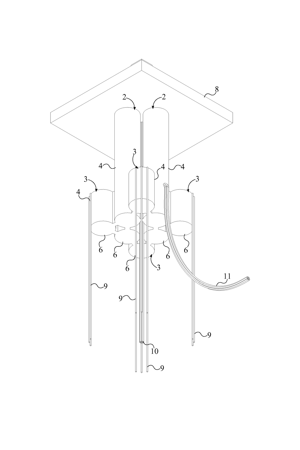
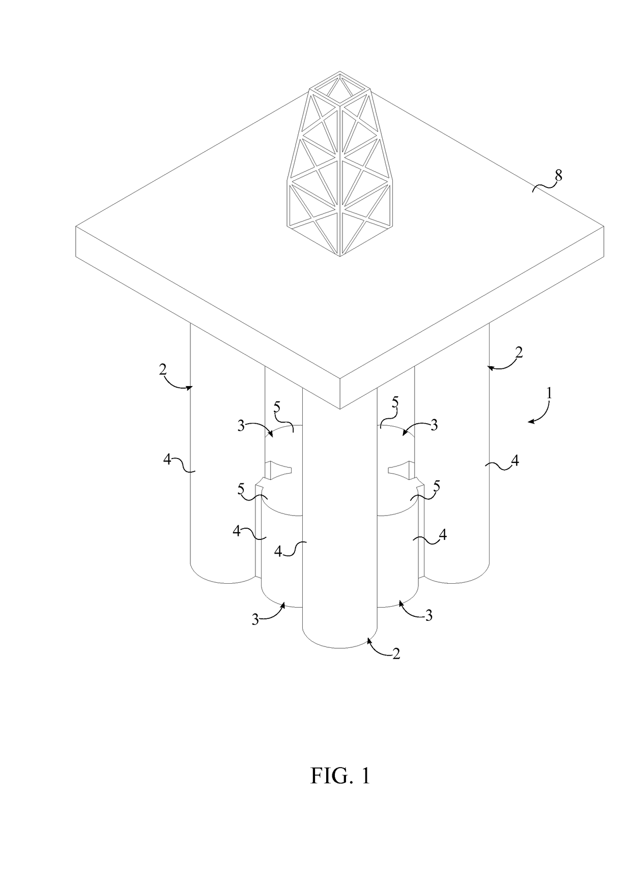
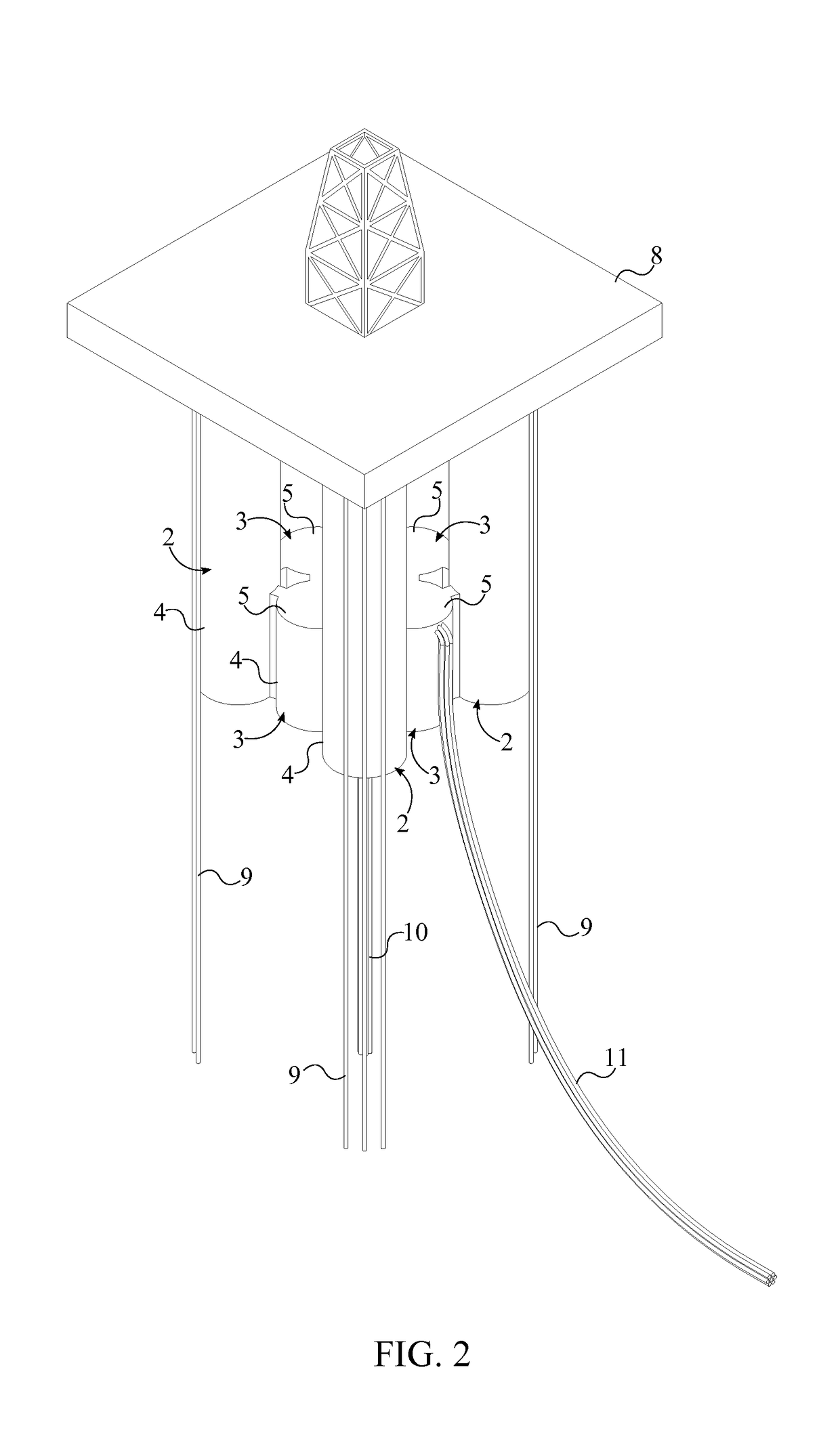
[0026]With reference to FIGS. 1-5, the present invention is a multi-column tension leg platform that may be used to support oil and natural gas production, drilling, wind farms, and other offshore activities. The present invention comprises a hull 1 and a topside 8. The hull 1 is a large structure that is designed to float on a body of water and support the topside 8. The topside 8 is a large platform that is situated on top of the hull and provides a deck for supporting workers, equipment, utilities needed for a specific job. The hull 1 comprises a plurality of flotation columns 2 and a plurality of pontoons 3. Both the plurality of flotation columns 2 and the plurality of pontoons 3 are used to supply the necessary buoyant force to keep the present invention afloat. The plurality of flotation columns 2...


PUM


Abstract

A multi-column tension leg platform is an offshore floating structure that is used to facilitate production of natural resources contained below the seabed. The multi-column tension leg platform includes a hull which is used to keep the entire structure afloat. The structure also includes a topside which is mounted to the top of the hull. The topside is used as a surface for supporting workers and equipment. The hull is made up of a plurality of flotation columns and a plurality of pontoons. Both the plurality of flotation columns and the plurality of pontoons are positioned about a vertical central axis of the topside. The plurality of flotation columns and the plurality of pontoons are buoyant structures that are aligned vertically and are used to keep the topside above water. The plurality of pontoons is mounted amongst the plurality of flotation columns.

Description

[0001]The current application claims a priority to the U.S. Provisional Patent application Ser. No. 61 / 990,471 filed on May 8, 2014 and claims a priority to the U.S. Provisional Patent application Ser. No. 62 / 049,410 filed on Sep. 12, 2014.FIELD OF THE INVENTION[0002]The present invention relates generally to floating offshore structures. More specifically, the present invention is a buoyant semi-submersible offshore platform which uses vertically configured flotation columns and pontoons to stay afloat. The present invention utilizes a unique arrangement of said flotation columns and pontoons to facilitate numerous anchoring and production methods.BACKGROUND OF THE INVENTION[0003]The present invention relates to improvements in motion characteristics, fabrication method, and the hull arrangement of a floating system intended for operating at sea with wet or dry-tree risers. The hull improvement in the present invention is related to a pontoon arrangement which makes the fabrication...

Claims


Application Information

Patent Timeline
Patent Type & Authority Patents(United States)
IPC IPC(8): B63B35/44B63B21/50B63B35/34B63B1/10B63B1/12
CPCB63B35/4413B63B1/107B63B1/125B63B21/502B63B35/34B63B35/44B63B2001/126B63B2001/128
Inventor TAHAR, ARCANDRA
Owner TAHAR ARCANDRA
Learn More