Sheet transfer device

a transfer device and sheet technology, applied in the direction of article feeders, transportation and packaging, thin material processing, etc., can solve the problems of jammed sheet being difficult to take out, drawing out drawer units, and affecting the safety of the device, so as to improve the safety and reliability of the device

Active Publication Date: 2017-03-28
RISO KAGAKU CORP
View PDF5 Cites 2 Cited by
  • Summary
  • Abstract
  • Description
  • Claims
  • Application Information

AI Technical Summary

Benefits of technology

[0015]An object of the disclosure is to provide a sheet transfer device which allows a sheet, if jammed across the sheet transfer device and its adjacent sheet transfer device arranged along a sheet transfer route in an image forming apparatus while being transferred along the sheet transfer route, to be easily taken out from the devices without leaving any part of the jammed sheet in the devices and which allows the sheet to be easily taken out while being designed such that a member arranged in the sheet transfer device occupies only a small area when being drawn out to protrude from the device in the take out of the jammed sheet.
[0017]In configuration described above, by drawing out the first divided sheet guide plate from the inside of the device and turning and opening the second divided sheet guide plate in the direction away from the other sheet transfer guide plate, the jammed sheet left on the second divided sheet guide plate side can be easily taken out with the first divided sheet guide plate occupying only a small area in the draw-out.
[0019]In the configuration described above, when the user carelessly or intentionally pushes the first divided sheet guide plate in the opposite direction to the draw-out direction with the second divided sheet guide plate being turned in the direction away from the other sheet transfer guide plate, the second divided sheet guide plate rides on and collides with the first divided sheet guide plate due to the presence of the push-in prohibiting portion formed in the first divided sheet guide plate or the second divided sheet guide plate. Accordingly, the push-in operation of the first divided sheet guide plate can be prohibited and the second divided sheet guide plate can be prevented from being housed in the device.
[0020]Accordingly, an abnormal state where the second divided sheet guide plate is placed on the first divided sheet guide plate in an overlapping manner does not occur when the first divided sheet guide plate is pushed toward the proper position in the device with the second divided sheet guide plate being open, and the safety and reliability of the device can be improved.

Problems solved by technology

When sheet jam occurs, a controller stops all of the sheets being transferred in the main body.
However, if the jammed sheet existing across the drawer unit and the main body is moved to completely enter the drawer unit or the main body, the jamming state of the sheet may become worse.
Accordingly, the jammed sheet may be difficult to take out if the unit is heavy.
Moreover, when the drawer unit is drawn out substantially horizontally to a position in front of the apparatus to take out the jammed sheet, the drawn-out drawer unit inevitably occupies as large an area as an exterior size of the drawer unit.

Method used


Image

  • Sheet transfer device
  • Sheet transfer device
  • Sheet transfer device

Examples


first embodiment

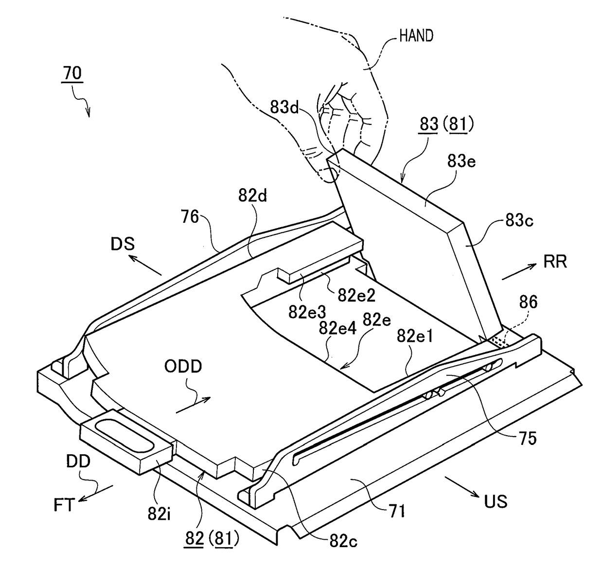
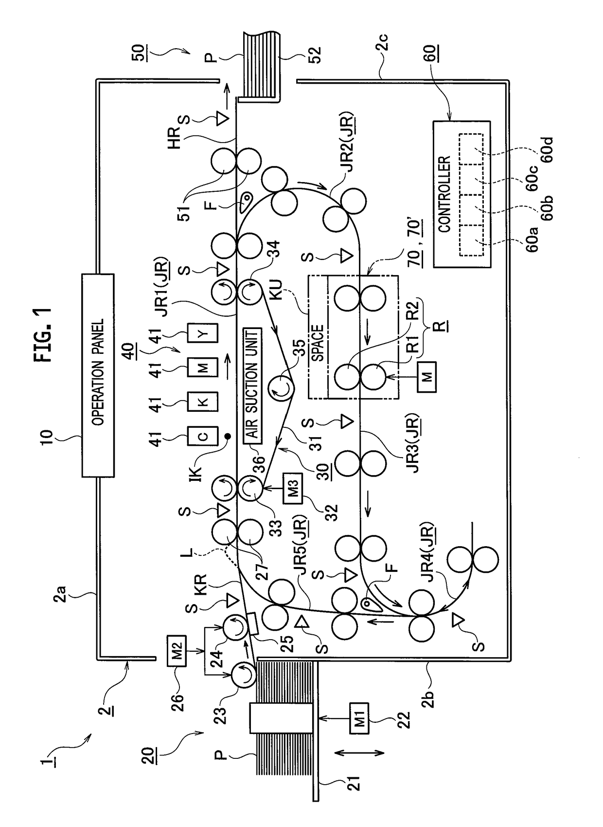
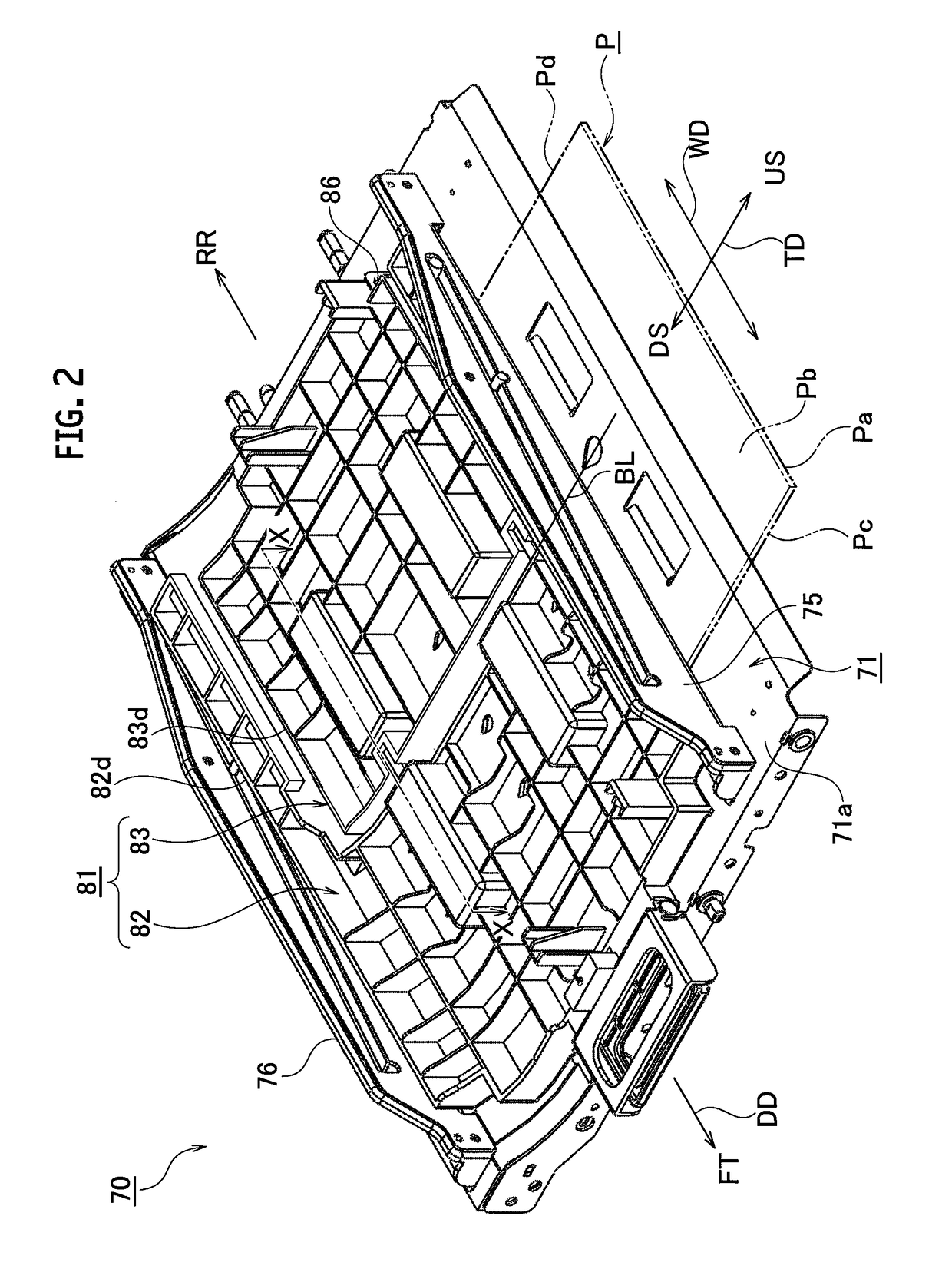
[0071]A configuration of the sheet transfer device 70 in the first embodiment is described by using aforementioned FIG. 1 and newly-presented FIGS. 2 to 7.

[0072]FIG. 2 is a perspective view of the sheet transfer device 70. FIG. 3 is a perspective view of a drive-side sheet transfer guide plate 71 (second sheet transfer guide plate) shown in FIG. 2. FIG. 4 is a perspective view of a driven-side sheet transfer guide plate 81 (82 and 83) (first sheet transfer guide plate) shown in FIG. 2. FIG. 5 is a perspective view of a first divided sheet guide plate 82 of the driven-side sheet transfer guide plate 81. FIG. 6 is a perspective view of a second divided sheet guide plate 83 of the driven-side sheet transfer guide plate 81. FIG. 7 is a plan view schematically showing a state where a push-in prohibiting portion 82e3 connected to an upper portion of a downstream wing portion 82e2 of the first divided sheet guide plate 82 overlaps a downstream outer surface 83d of the second divided sheet ...

second embodiment

[0183]FIG. 12 is a perspective view of the sheet transfer device 70′ in the second embodiment.

[0184]A configuration of the sheet transfer device 70′ shown in FIG. 12 is partially different from the configuration of the sheet transfer device 70 (FIGS. 1 and 2) of the first embodiment only in first and second divided sheet guide plates 82′ and 83′ forming a driven-side sheet transfer guide plate (hereafter, referred to as driven-side sheet guide plate) 81′ facing the drive-side sheet transfer guide plate (hereafter, referred to as drive-side sheet guide plate) 71.

[0185]In the second embodiment, the same constitutional members and the same shapes as those in the first embodiment are denoted by the same reference numerals, and the aforementioned constitutional members are described as necessary for the sake of convenience of description. Constitutional members different from those in the first embodiment are denoted by new reference numerals and description is given mainly of points dif...


PUM


Abstract

A first sheet transfer guide plate includes a first divided sheet guide plate and a second divided sheet guide plate separably connected to each other. The first divided sheet guide plate is capable of being drawn out by being moved relative to the second divided sheet guide plate in a sheet width direction orthogonal to a sheet transfer direction. The second divided sheet guide plate with the first divided sheet guide plate drawn out is turnable about a turning shaft in a direction away from a second sheet transfer guide plate. The turning shaft is arranged parallel to the sheet transfer direction and arranged in a rear end of the second divided sheet guide plate. The rear end is located opposite to a side toward which the first divided sheet guide plate is drawn out.

Description

CROSS REFERENCE TO RELATED APPLICATION[0001]This application is based upon and claims the benefit of priority from the prior Japanese Patent Application No. 2014-238670, filed on Nov. 26, 2014, the entire contents of which are incorporated herein by reference.BACKGROUND[0002]1. Technical Field[0003]The disclosure relates to a sheet transfer device which allows a sheet, if jammed across the sheet transfer device and its adjacent sheet transfer device arranged along a sheet transfer route in an image forming apparatus while being transferred along the sheet transfer route, to be easily taken out from the devices without leaving the jammed sheet in the devices.[0004]2. Related Art[0005]Generally, the sheet transfer device configured to transfer sheets is applied to an image forming apparatus such as a printer configured to print images and characters on sheets and a photocopier configured to duplicate images and characters on sheets.[0006]Japanese Unexamined Patent Application Publicat...

Claims


Application Information

Patent Timeline
Patent Type & Authority Patents(United States)
IPC IPC(8): B65H5/06B65H5/38
CPCB65H5/38B65H5/062B65H2402/31B65H2402/32B65H2402/441B65H2402/61B65H2404/611B65H2801/06B65H2402/60
Inventor ETSUKI, RYOHEI
Owner RISO KAGAKU CORP
Why Eureka
Try Eureka