Rotary encoder having periodic and non-periodic tracks

a rotary encoder and periodic technology, applied in the field of optical type rotary encoders, can solve the problems inability to calculate non-periodic errors, and inability to deal with so as to suppress the effect of deterioration of detection precision

Active Publication Date: 2017-03-28
FANUC LTD
View PDF16 Cites 0 Cited by
  • Summary
  • Abstract
  • Description
  • Claims
  • Application Information

AI Technical Summary

Benefits of technology

[0009]A rotary encoder which can suppress deterioration of detection precision due to retro reflected light at a non-transmitting part of a rotary disk has been sought.

Problems solved by technology

If retro reflected light at a certain optical track enters another optical track in this way, a modulated signal corresponding to the optical track may be superposed, and therefore the detection precision of the rotary encoder may be deteriorated.
However, the signal processing system of JP2003-254785A cannot calculate non-periodic error.
Therefore, the signal processing system of JP2003-254785A can deal with deterioration of detection precision due to retro reflected light at an optical track which has a periodic pattern, but cannot deal with deterioration of detection precision due to retro reflected light of an optical track which has a non-periodic pattern.
However, according to the above arrangement, the rotary disk may have larger areas which cannot be provided with optical tracks, and therefore it is not possible to make effective use of the regions illuminated by the light emitting diode.

Method used


Image

  • Rotary encoder having periodic and non-periodic tracks
  • Rotary encoder having periodic and non-periodic tracks
  • Rotary encoder having periodic and non-periodic tracks

Examples


Embodiment Construction

[0026]Below, an embodiment of the present invention will be explained in detail with reference to the drawings. In the drawings, similar component elements are assigned similar reference notations. Note that the following explanation does not limit the technical scope of the inventions which are described in the claims or the meaning of terms etc.

[0027]Referring to FIG. 1 to FIG. 5, a rotary encoder of one embodiment of the present invention will be explained. The rotary encoder of the present embodiment is an optical type sensor which detects the rotational angle of a drive shaft of an electric motor or a rotating shaft which is connected to another type rotatable body.

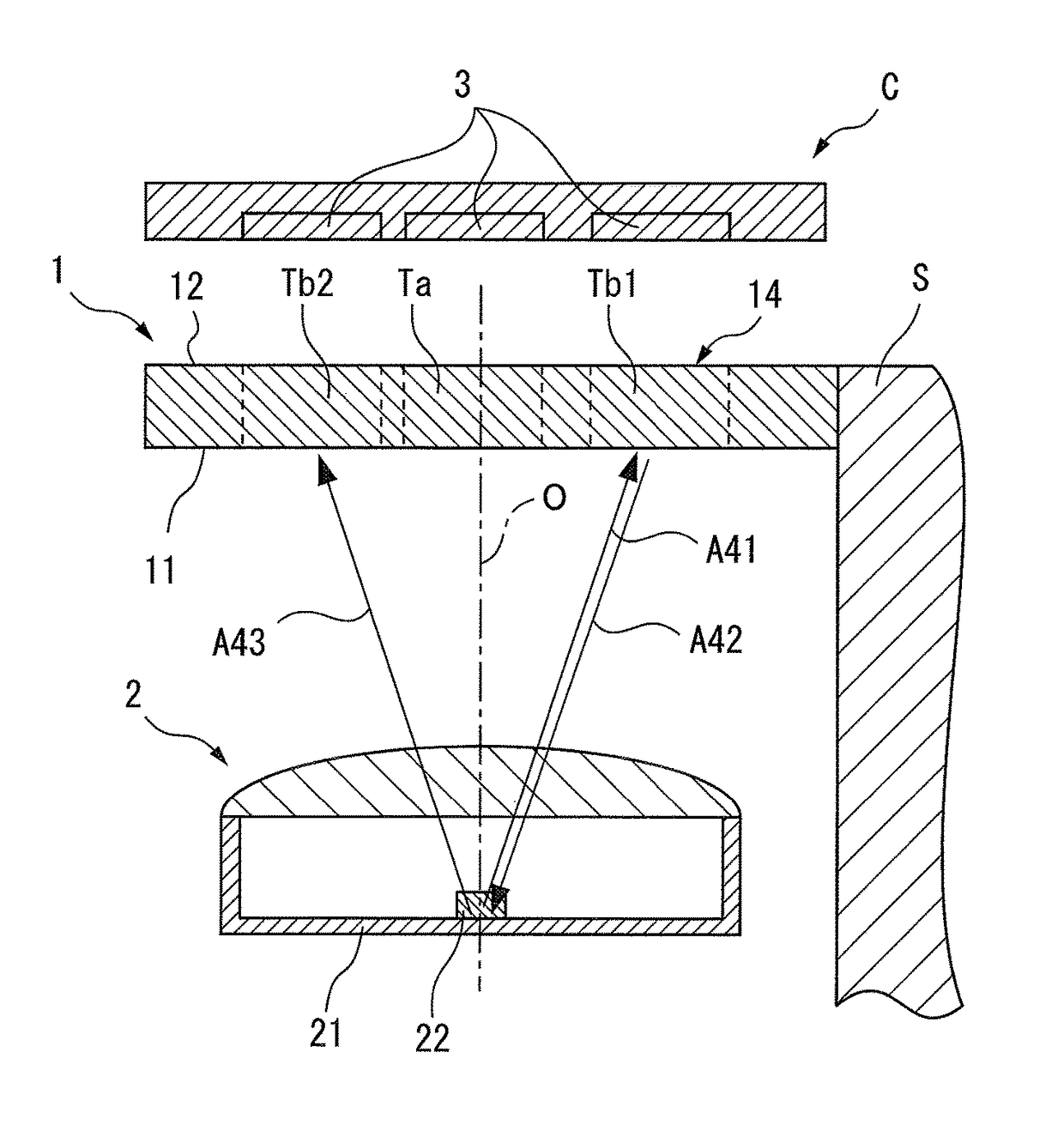
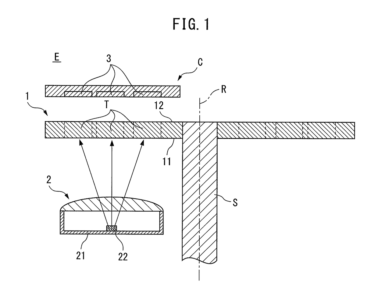
[0028]In particular, the rotary encoder of the present embodiment is a light transmitting type rotary encoder, and is provided with a light emitting diode which faces a bottom surface of a rotary disk and light receiving elements which face a top surface of the rotary disk. FIG. 1 is a cross-sectional view along the ...


PUM


Abstract

In a rotary encoder of the present invention, each track of a rotary disk has transmitting parts and non-transmitting parts alternately arranged in the circumferential direction. Each non-transmitting part has a plurality of projecting parts which are arranged side by side in the circumferential direction. Each projecting part has a pair of reflecting surfaces which retro reflect incident light toward a light emitting part. A plurality of tracks include a periodic track where transmitting parts and non-transmitting parts are arranged with a periodic pattern and non-periodic tracks where transmitting parts and non-transmitting parts are arranged in a non-periodic pattern. The periodic track and non-periodic track are respectively arranged at positions in the radial direction where further reflected light at the light emitting part after retro reflection at the reflecting surfaces of the non-periodic track will not enter the periodic track.

Description

BACKGROUND OF THE INVENTION[0001]1. Field of the Invention[0002]The present invention relates to an optical type rotary encoder for detecting a rotational angle of a rotatable body.[0003]2. Description of the Related Art[0004]In the field of industrial machinery, an optical type rotary encoder has been used as a sensor for detecting a rotational angle of a drive shaft of an electric motor or a rotatable body which is driven by the electric motor. In general, optical type rotary encoders are classified into transmission types which use modulated light which was transmitted through a rotary disk as the basis to detect the rotational angle of a rotatable body, and reflection types which use modulated light which was reflected at a rotary disk as the basis to detect the rotational angle of a rotatable body.[0005]In general, a transmission type rotary encoder comprises a light emitting diode, a rotary disk which is provided with a plurality of optical tracks for converting emitted light ...

Claims


Application Information

Patent Timeline
Patent Type & Authority Patents(United States)
IPC IPC(8): G01D5/34G01D5/347
CPCG01D5/34792G01D5/3473
Inventor OOTAKE, NOBUYUKI
Owner FANUC LTD
Why Eureka
Try Eureka