Oilfield apparatus and methods of use

a technology of oilfield equipment and oilfield, applied in earth drilling, well accessories, sealing/packing, etc., can solve the problems of compromising the original design of the christmas tree, complex and carefully designed christmas tree equipment, and avoiding deviations in the location of critical components

Active Publication Date: 2017-04-04
ENPRO SUBSEA
View PDF40 Cites 8 Cited by
  • Summary
  • Abstract
  • Description
  • Claims
  • Application Information

AI Technical Summary

Benefits of technology

[0003]There are a number of reasons why it is desirable to access a flow system in an oil and gas production system (generally referred to as an “intervention”). In the context of this specification, the term “fluid intervention” is used to encapsulate any method which accesses a flow line, manifold or tubing in an oil and gas production, injection or transportation system. This includes (but is not limited to) accessing a flow system for fluid sampling, fluid diversion, fluid recovery, fluid injection, fluid circulation, fluid measurement and / or fluid metering. This can be distinguished from full well intervention operations, which generally provide full (or near full) access to the wellbore. Full well intervention processes and applications are often technically complex, time-consuming and have a different cost profile to fluid intervention operations. It will be apparent from the following description that the present invention has application to full well intervention operations. However, it is an advantage of the invention that full well intervention may be avoided, and therefore preferred embodiments of the invention provide methods and apparatus for fluid intervention which do not require full well intervention processes.
[0004]International patent application numbers WO00 / 70185, WO2005 / 047646 and WO2005 / 083228 describe a number of configurations for accessing a hydrocarbon well via a choke body on a Christmas tree. Although a choke body provides a convenient access point in some applications, the methods of WO00 / 70185, WO2005 / 047646, and WO2005 / 083228 do have a number of disadvantages. Firstly, a Christmas tree is a complex and carefully-designed piece of equipment. The choke performs an important function in production or injection processes, and its location on the Christmas tree is selected to be optimal for its intended operation. Where the choke is removed from the choke body, as proposed in the prior art, the choke must be repositioned elsewhere in the flow system to maintain its functionality. This compromises the original design of the Christmas tree, as it requires the choke to be located in a sub-optimal position.
[0005]Secondly, a choke body on a Christmas tree is typically not designed to support dynamic and / or static loads imparted by intervention equipment and processes. Typical loads on a choke body in normal use would be of the order of 0.5 to 1 tonnes, and the Christmas tree is engineered with this in mind. In comparison, a typical flow metering system as contemplated in the prior art may have a weight of the order of 2 to 3 tonnes, and the dynamic loads may be more than three times that value. Mounting a metering system (or other fluid intervention equipment) on the choke body therefore exposes that part of the Christmas tree to loads in excess of those that it is designed to withstand, creating a risk of damage to the structure. This problem may be exacerbated in deepwater applications, where even greater loads may be experienced due to thicker and / or stiffer components used in the subsea infrastructure.
[0006]In addition to the load restrictions identified above, positioning the flow intervention equipment on the choke body may limit the access available to large items of process equipment and / or access of divers or remotely operated vehicles (ROVs) to the process equipment or other parts of the tree.
[0007]Furthermore, modifying the Christmas tree so that the chokes are in non-standard positions is generally undesirable. It is preferable for divers and / or ROV operators to be completely familiar with the configuration of components on the Christmas tree, and deviations in the location of critical components are preferably avoided.
[0008]Another drawback of the prior art proposals is that not all Christmas trees have chokes integrated with the system; approaches which rely on Christmas tree choke body access to the flow system are not applicable to these types of tree.

Problems solved by technology

Full well intervention processes and applications are often technically complex, time-consuming and have a different cost profile to fluid intervention operations.
Firstly, a Christmas tree is a complex and carefully-designed piece of equipment.
This compromises the original design of the Christmas tree, as it requires the choke to be located in a sub-optimal position.
Secondly, a choke body on a Christmas tree is typically not designed to support dynamic and / or static loads imparted by intervention equipment and processes.
Mounting a metering system (or other fluid intervention equipment) on the choke body therefore exposes that part of the Christmas tree to loads in excess of those that it is designed to withstand, creating a risk of damage to the structure.
This problem may be exacerbated in deepwater applications, where even greater loads may be experienced due to thicker and / or stiffer components used in the subsea infrastructure.
In addition to the load restrictions identified above, positioning the flow intervention equipment on the choke body may limit the access available to large items of process equipment and / or access of divers or remotely operated vehicles (ROVs) to the process equipment or other parts of the tree.
Furthermore, modifying the Christmas tree so that the chokes are in non-standard positions is generally undesirable.
Another drawback of the prior art proposals is that not all Christmas trees have chokes integrated with the system; approaches which rely on Christmas tree choke body access to the flow system are not applicable to these types of tree.

Method used


Image

  • Oilfield apparatus and methods of use
  • Oilfield apparatus and methods of use
  • Oilfield apparatus and methods of use

Examples


Embodiment Construction

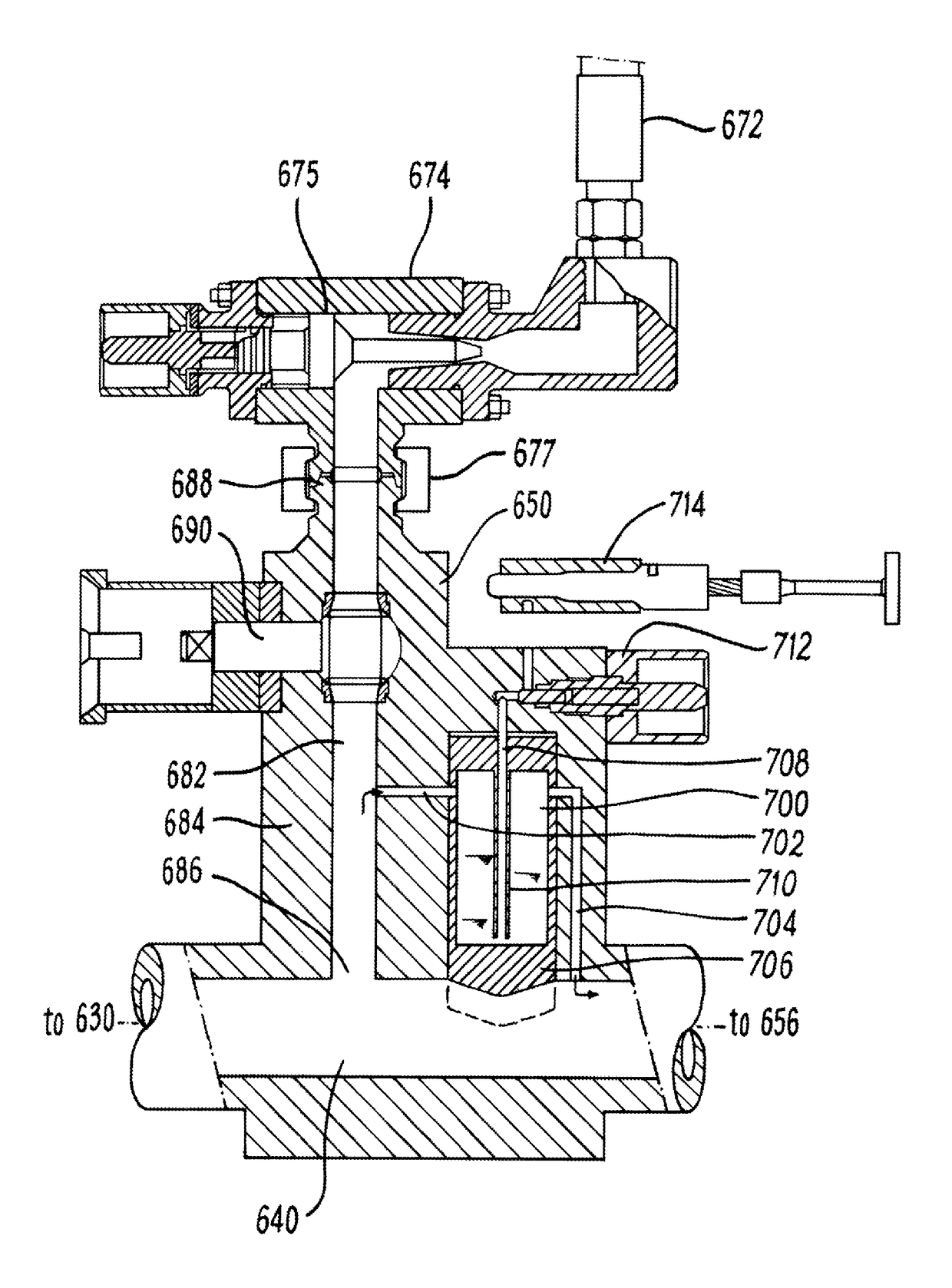
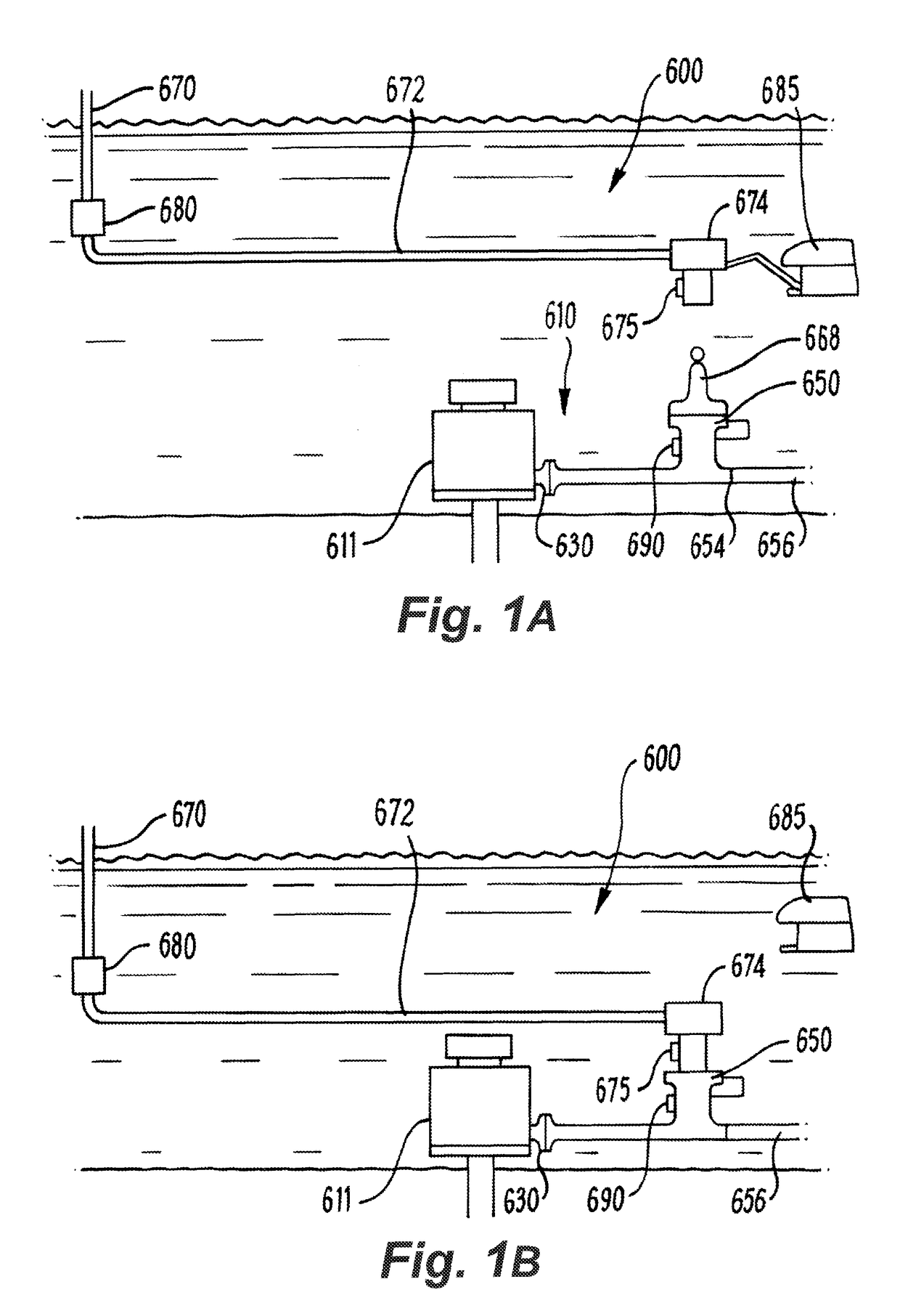
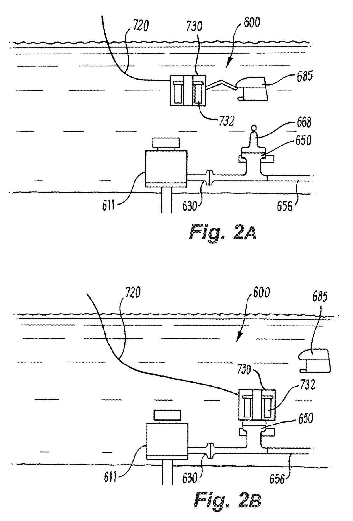
[0147]Referring firstly to FIGS. 1 to 3, a combined injection and sampling system will be described. The system, generally depicted at 600, is shown schematically in different stages of a subsea injection operation in a well squeeze application in FIGS. 1A and 1B and in a sampling mode as described below with reference to FIGS. 2A and 2B. A hub 650, configured as a combined sampling and injection hub used in the methods of FIGS. 1 and 2, is shown in more detail in FIG. 3.

[0148]The system 600 comprises a subsea flow system 610 which includes subsea manifold 611. The subsea manifold 611 is a conventional vertical dual bore Christmas tree (with internal tree components omitted for simplicity), and the system 600 utilises a hub 650 to provide access to the flow system 610. A flowline connector 630 of a production branch outlet conduit (not shown) is connected to the hub 650 which provides a single access point to the system. At its opposing end, the hub 650 comprises a standard flowline...


PUM


Abstract

The invention in one of its aspects provides a connection apparatus for a subsea hydraulic circuit and method of use in a sampling application. The apparatus comprises a longitudinal body configured to be removably docked with a subsea hydraulic circuit receptacle. The body comprises a plurality of radial ports axially displaced along the body, and an axial bore accommodating a spool having at least one fluid barrier. The spool and fluid barrier are actuable to be axially moved in the bore to control axial flow paths along the bore between the plurality of radial ports. The apparatus may be configured as a sampling hot stab in an application to sampling a production fluid from a subsea hydrocarbon production system.

Description

[0001]The present invention relates to oilfield apparatus and methods of use, and in particular to a sampling apparatus (such as a sampling chamber, a sampling test circuit, sampling tools), and methods of use for fluid intervention and sampling in oil and gas production or injection systems. The invention has particular application to subsea oil and gas operations, and aspects of the invention relate specifically to methods and apparatus for combined fluid injection and sampling applications.BACKGROUND TO THE INVENTION[0002]In the field of oil and gas exploration and production, it is common to install an assembly of valves, spools and fittings on a wellhead for the control of fluid flow into or out of the well. Such flow systems typically include a Christmas tree, which is a type of fluid manifold used in the oil and gas industry in surface well and subsea well configurations. A Christmas tree has a wide range of functions, including chemical injection, well intervention, pressure...

Claims


Application Information

Patent Timeline
Patent Type & Authority Patents(United States)
IPC IPC(8): E21B33/076E21B49/08E21B33/035E21B33/038
CPCE21B33/076E21B33/035E21B33/038E21B49/084E21B49/086E21B33/0387
Inventor DONALD, IANREID, JOHN
Owner ENPRO SUBSEA
Why Eureka
Try Eureka