Shroud arrangement for a gas turbine engine

a gas turbine engine and shielding technology, applied in the direction of machines/engines, leakage prevention, non-positive displacement fluid engines, etc., can solve the problems of increasing the cooling efficiency of components, reducing and wasting effort, so as to achieve the effect of improving the efficiency of the engin

Active Publication Date: 2017-04-04
ROLLS ROYCE PLC
View PDF15 Cites 18 Cited by
  • Summary
  • Abstract
  • Description
  • Claims
  • Application Information

AI Technical Summary

Benefits of technology

[0007]The provision of a plate having two cooling circuits with tortuous paths allows the use of two separate sources of cooling air which can provide an efficiency benefit for the engine.
[0021]Each U-bend may include at least one bifurcating feature to help prevent flow separation around the U-bend.

Problems solved by technology

However, increasing cooling of components generally represents a reduction in efficiency and so much effort is spent in finding a satisfactory trade-off between turbine entry temperature, the life of a cooled turbine component and specific fuel consumption.

Method used


Image

  • Shroud arrangement for a gas turbine engine
  • Shroud arrangement for a gas turbine engine
  • Shroud arrangement for a gas turbine engine

Examples


Embodiment Construction

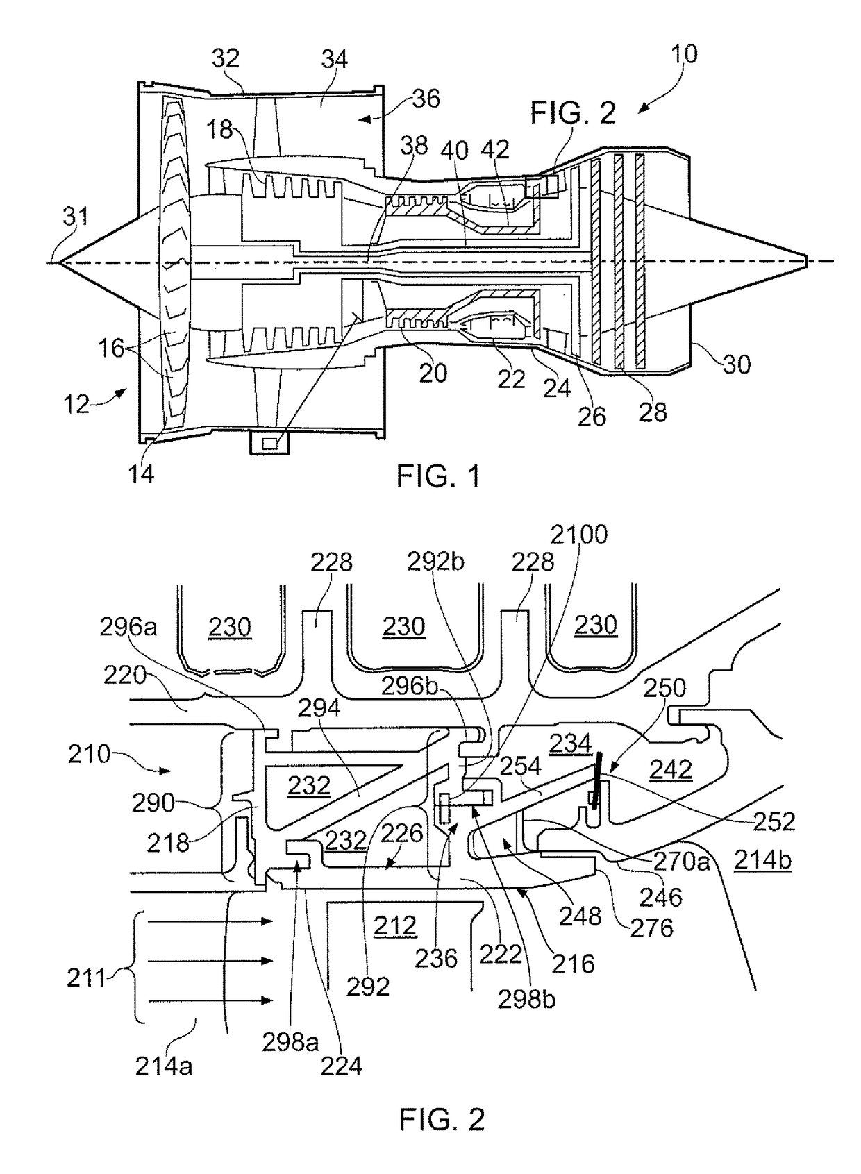
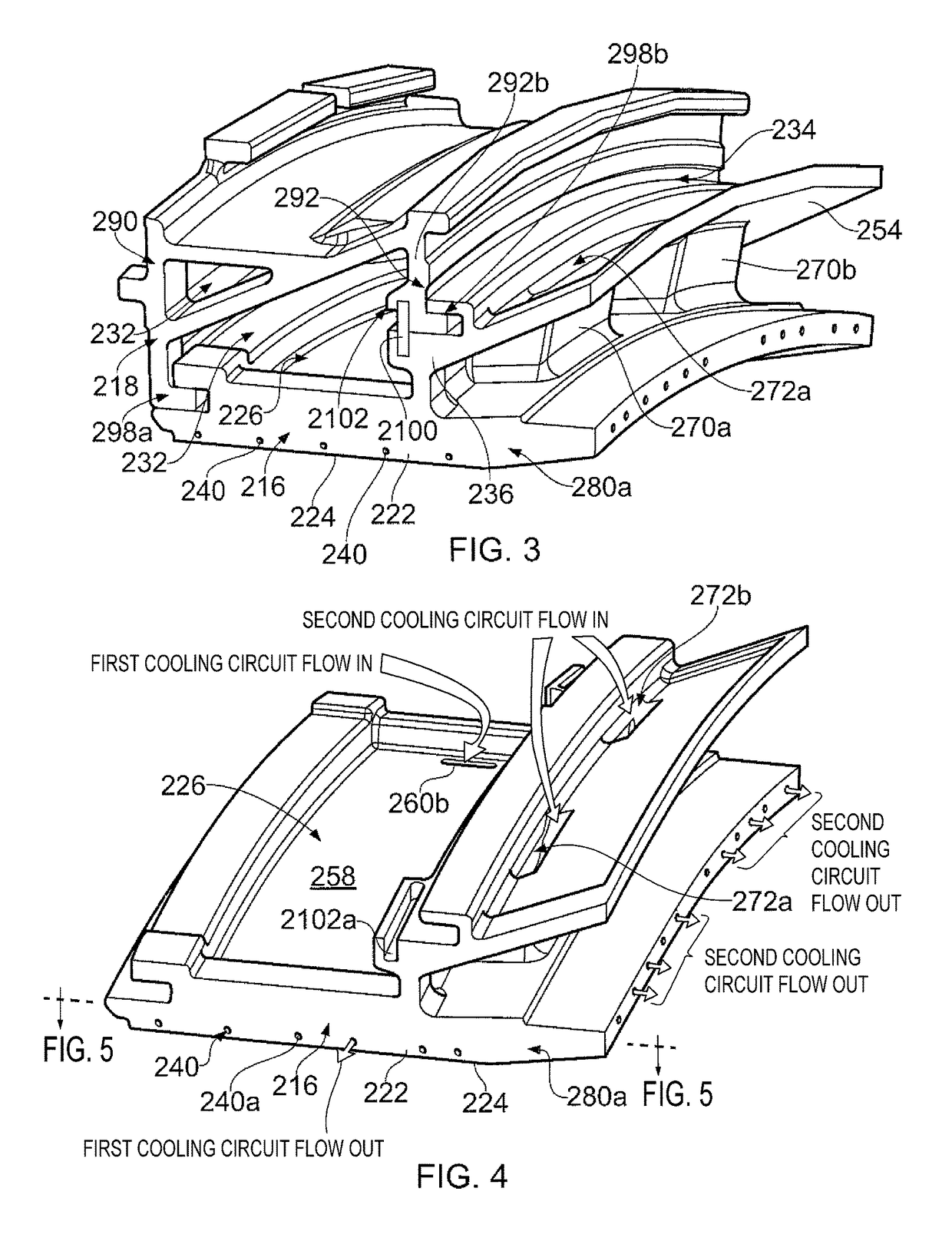
[0035]FIG. 2 provides a cross-section of the shroud arrangement 210 and surrounding structure which can be located within the architecture of a substantially conventional gas turbine at a location as highlighted in FIG. 1. FIG. 3 shows a perspective schematic view of a shroud cassette which includes a seal segment 216 and carrier segment 218. FIG. 4 shows a perspective schematic representation of the seal segment 216 only.

[0036]The shroud arrangement 210 forms part of the turbine section of a gas turbine engine similar to that shown in FIG. 1 and defines the boundary of the hot gas flow path 211 thereby helping to prevent gas leakage and provide thermal shielding for the outboard structures of the turbine.

[0037]The turbine (rotor) blade 212 sits radially inwards of the shroud arrangement 210 and is one of a plurality conventional radially extending blades which are arranged circumferentially around a supporting disc (not shown) which is rotatable about the principal axis 31 of the e...


PUM


Abstract

A seal segment for bounding a hot gas flow path within a gas turbine engine, including: a plate having an inboard side which bounds the hot gas flow path in use, an outboard side and fore and aft cooling circuits, wherein the fore and aft cooling circuits are fluidically separated from one another within the plate and each has at least one tortuous path between an inlet on the outboard side of the plate and an exhaust.

Description

TECHNICAL FIELD OF INVENTION[0001]This invention relates to shroud arrangement for a gas turbine engine. In particular, the invention relates to a shroud arrangement which is cooled using two sources of cooling air.BACKGROUND OF INVENTION[0002]FIG. 1 shows a ducted fan gas turbine engine 10 comprising, in axial flow series: an air intake 12, a propulsive fan 14 having a plurality of fan blades 16, an intermediate pressure compressor 18, a high-pressure compressor 20, a combustor 22, a high-pressure turbine 24, an intermediate pressure turbine 26, a low-pressure turbine 28 and a core exhaust nozzle 30. The fan, compressors and turbine are all rotatable about a principal axis 31 of the engine 10. A nacelle 32 generally surrounds the engine 10 and defines the intake 12, a bypass duct 34 and a bypass exhaust nozzle 36.[0003]Air entering the intake 12 is accelerated by the fan 14 to produce a bypass flow and a core flow. The bypass flow travels down the bypass duct 34 and exits the bypas...

Claims


Application Information

Patent Timeline
Patent Type & Authority Patents(United States)
IPC IPC(8): F04D31/00F01D11/08F01D25/12
CPCF01D25/12F01D11/08F05D2240/11
Inventor TAYLOR, RUPERT JOHN
Owner ROLLS ROYCE PLC
Why Eureka
Try Eureka