Compact two probe impedance tuner

Inactive Publication Date: 2017-04-11
TSIRONIS CHRISTOS
View PDF2 Cites 5 Cited by
  • Summary
  • Abstract
  • Description
  • Claims
  • Application Information

AI Technical Summary

Problems solved by technology

Nevertheless capacitive contact means extreme requirement in sidewall planarity and straightness to keep the capacitive contact constant for the whole length and depth of the slabline as the probe travels.

Method used


Image

  • Compact two probe impedance tuner
  • Compact two probe impedance tuner
  • Compact two probe impedance tuner

Examples


Embodiment Construction

[0028]This invention discloses a new low footprint slide screw impedance tuner comprising two independent tuning probes, the compact two-probe circular tuner. The essential components of this new structure are:[0029]a. A double-decker (sandwich) set of circular horizontal slablines with circular (toroid) center conductors.[0030]b. Two independently driven eccentrically rotating disc-(tuning) probes.[0031]c. Two mobile carriages in form of independently driven and rotating radial arms.[0032]d. Stepper motors, electronic control and mechanical control gear.

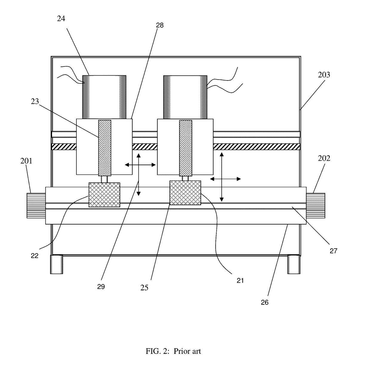
[0033]The effect of using the new structure is reducing the overall horizontal length (footprint) of a prior art (linear) two-probe tuner by a factor, which depends on the minimum frequency of operation, and ranges between 9.5 (at Fmin=100 MHz) and 4.2 (at Fmin=800 MHz); (compare FIGS. 2 and 8 and see ref. 2); table I summarizes this:

[0034]

TABLE IComparison of total length of prior art linear and new circular two-probe tunersMinimum...


PUM


Abstract

An automated “double-decker” slide screw impedance tuner uses two tuning probes, independently movable inside two stacked circular slablines, which lie flat on the bench table. The eccentrically self-rotating disc probes are mounted at the end of rotating radial arm-carriages, the total mechanism operating in a planetary configuration. The radial arms are mounted one above and one below the whole structure. The rotation of the arms control the phase of Gamma and the self-rotation of the disc probes controls the amplitude. The length (footprint) of the tuner, compared with traditional “linear” tuners, is reduced by a factor of 5 to 9, depending of the minimum frequency of operation.

Description

PRIORITY CLAIM[0001]This application claims priority on provisional application 62 / 034,201, filed on Aug. 7, 2014, titled “Compact Two Probe Impedance Tuner”.CROSS-REFERENCE TO RELATED ARTICLES[0002]1. Load Pull Measurements, http: / / en.wikipedia.org / wiki / Load_pull.[0003]2. “Computer Controlled Microwave Tuner—CCMT”, Product Note 41, Focus Microwaves, January 1998.[0004]3. Standing wave ratio, VSWR, https: / / en.wikipedia.org / wiki / Standing_wave_ratio.[0005]4. “High Resolution Tuners Eliminate Load Pull Performance Errors”, Application Note 15, Focus Microwaves, January 1995.BACKGROUND OF THE INVENTION[0006]This invention relates to RF load and source pull testing of medium and high power RF transistors and amplifiers using remotely controlled electro-mechanical impedance tuners.[0007]Modern design of high power RF amplifiers and mixers, used in various communication systems, requires accurate knowledge of the active device's (microwave transistor's) characteristics. In such circuits, i...

Claims


Application Information

Patent Timeline
Patent Type & Authority Patents(United States)
IPC IPC(8): H03H7/38H01P5/04G01R35/00H03H7/40H01P3/08
CPCH01P5/04G01R35/005H03H7/40H01P3/087
Inventor TSIRONIS, CHRISTOS
Owner TSIRONIS CHRISTOS
Why Eureka
Try Eureka