Ankle brace

a technology for ankles and heels, applied in the field of orthotics, can solve the problems of affecting the healing time of ankles and heels, affecting the patient's comfort, and requiring months of healing time before recovery, and achieve the effect of preventing extension or flexion of the foo

Active Publication Date: 2017-04-18
WEBER CHARLES W
View PDF12 Cites 2 Cited by
  • Summary
  • Abstract
  • Description
  • Claims
  • Application Information

AI Technical Summary

Benefits of technology

[0011]In a further aspect of the present invention the foot brace can incorporate a suspension / dampened hinge that permits infinitely varying degrees of articulation / weight to bear on the ankle joint and Achilles tendon as the injury heals.
[0012]An aspect of embodiments in accordance with the present invention is an ankle brace comprising: a pair of trusses for extending along both the inside and outside in a parallel manner from the front of the foot to the ankle and up to the lower shin; a metatarsal band attached to both of said pair of trusses for extending over the toes and lower foot; a shin band attached to both of said pair of trusses for extending over and across a lower, front portion of the shinbone; and a heel strap attached to said pair of trusses for extending around and receiving the back of a boot heel, whereby placement of the ankle brace over the front of a footwear boot and attachment of the heel strap to the back of the boot heel prevents extension or flexion of the foot.

Problems solved by technology

Although encouraged by their doctor and therapist to begin walking, these heavy plaster casts were not pleasant for the patient—in addition to the various discomforts of rigid casts, the weight of the cast when walking tended to cause fatigue and place strains on the affected leg muscles.
Ankle and heel injuries can require months of healing time before recovery is complete.
Of course, the application of too much weight or an appropriate weight but too quickly or in the wrong direction can reinjure the joint, extending the rehabilitation process.
The “walker” braces enable mobility; however, they do not provide much in the way of an enclosure for protecting the foot.

Method used


Image

  • Ankle brace
  • Ankle brace
  • Ankle brace

Examples


Embodiment Construction

[0021]The ankle brace is disclosed herein with respect to exemplary embodiments. The embodiments are disclosed for illustration of the ankle brace and a manner of operation, and are not limiting except as defined in the appended claims.

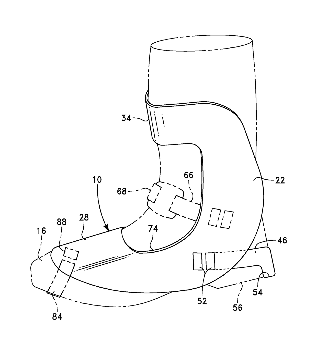
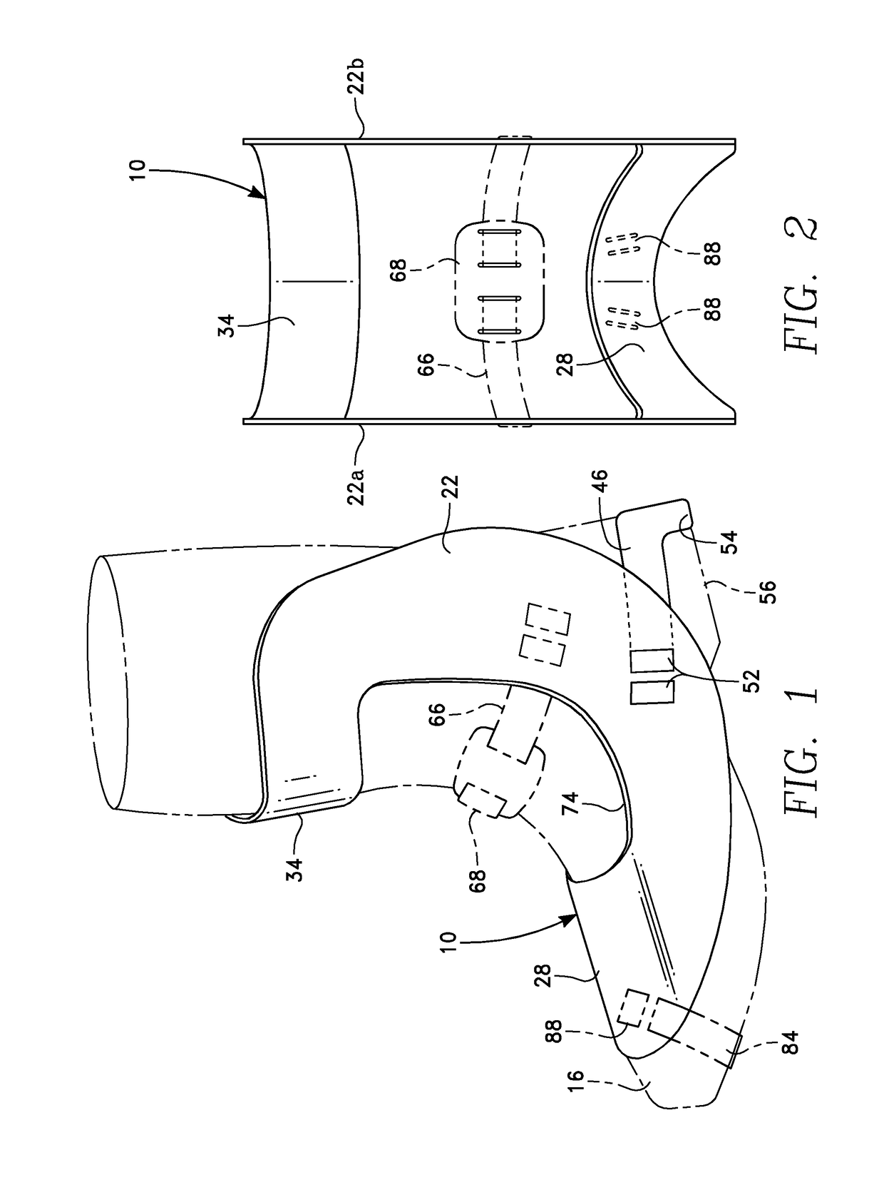
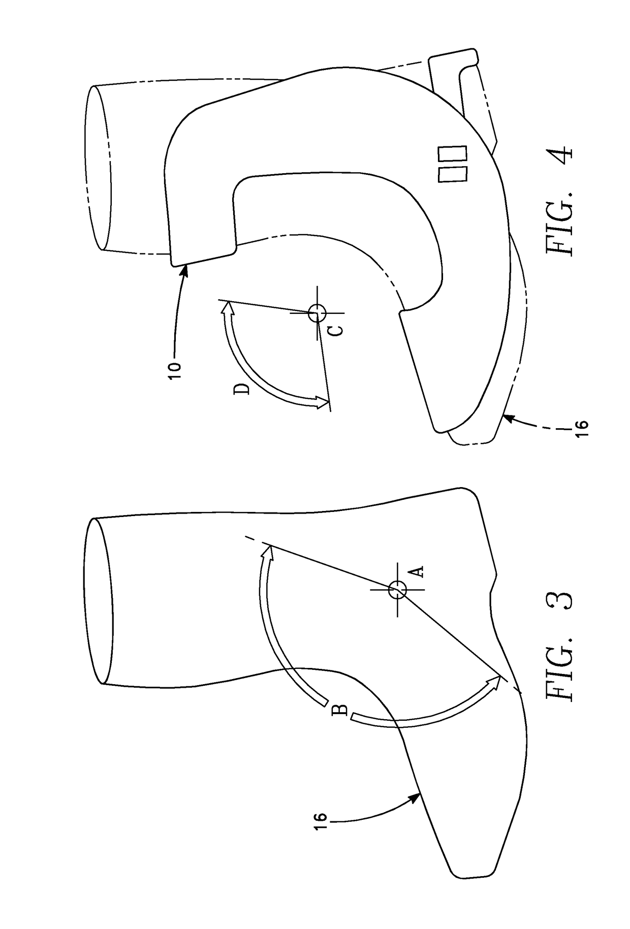
[0022]Reference is now made to the drawings wherein like structures refer to like parts throughout. In FIG. 1 an ankle brace 10 is placed over and secured to a boot 16 placed on the foot of a patient (not shown in the Figures), providing support for many of the ankle weight-bearing bones, ligaments, and tendons. The ankle brace 10 includes a pair of lateral trusses 22 (the ankle brace 10 is substantially symmetric and only one of the pair of trusses is shown in FIG. 1—while the pair of trusses 22a, 22b are shown in FIG. 2). Each of the trusses 22a, 22b extend on a separate side of the foot and leg, along both the medial border and the lateral border (see FIG. 2), from a location adjacent the toes, curving upwardly to a location on the lower leg that i...


PUM


Abstract

An ankle brace received by a footwear boot prevents extension or flexion of the foot while walking. The ankle brace includes a pair of side trusses joined at the top by a shin band and at the bottom by a metatarsal band. When placed on the boot the shin band extends over and across a lower front portion of the shin bone, the metatarsal band extends over the toes and lower foot, and the pair of trusses extend along the inside and outside in a parallel manner from the front of the foot to the ankle and up to the lower shin. A heel strap and heel cup attached to the pair of trusses extends around and receives the back of the boot, retaining the brace in place against the boot.

Description

RELATED APPLICATIONS[0001]The present application claims the benefit of priority under 35 USC §119(e) to U.S. Provisional Application No. 61 / 722,905, filed on Nov. 6, 2012, which is incorporated by reference herein for all that it contains.BACKGROUND OF THE INVENTION[0002]Field of the Invention[0003]The present invention relates to orthotic device, and more specifically to a brace used to immobilize a joint. More specifically, the present invention relates to a foot brace that is placed over a conventional footwear boot to prevent extension or flexion of the foot, enabling use of the boot while protecting the Achilles tendon or ankle during healing.[0004]Description of the Related Art[0005]Traditionally, severe heel and ankle injuries were first treated by encasement in a heavy plaster cast until healing was complete. Subsequent medical studies suggested the desirability of having the patient begin walking at an early stage of rehabilitation. The heavy plaster casts were modified by...

Claims


Application Information

Patent Timeline
Patent Type & Authority Patents(United States)
IPC IPC(8): A61F5/01A43B7/20A61F5/058
CPCA61F5/0111A61F5/0104A43B7/20A61F5/0585
Inventor WEBER, CHARLES W.
Owner WEBER CHARLES W
Why Eureka
Try Eureka