
Method for activating fuel cell

a fuel cell and activation technology, applied in the direction of fuel cells, fuel cell control, solid electrolyte fuel cells, etc., can solve the problems of disadvantageous power generation performance of a plurality of treated fuel cells, all fuel cells not necessarily showing etc., to achieve excellent power generation performance, prevent power generation performance variations, and the effect of the same power generation performan

Active Publication Date: 2016-05-17
HONDA MOTOR CO LTD
View PDF10 Cites 0 Cited by
  • Summary
  • Abstract
  • Description
  • Claims
  • Application Information

AI Technical Summary

Benefits of technology

The present invention provides a method for activating fuel cells that prevents power generation performance variations among multiple fuel cells. This method ensures that each fuel cell is sufficiently activated and exhibits an excellent power generation performance after activation treatment. Additionally, the activation degree of multiple fuel cells can be consistent, resulting in plural fuel cells with substantially the same power generation performances.

Problems solved by technology

In this case, even when a plurality of the fuel cells are subjected to the aging or activation treatment under the same conditions, all the fuel cells do not necessarily exhibit the same power generation performance.
This is because there are individual differences between components of the fuel cells.
As is clear from this, in the aging or activation treatment utilizing the time control, the power generation performance may vary among a plurality of the treated fuel cells disadvantageously.

Method used


Image

  • Method for activating fuel cell
  • Method for activating fuel cell
  • Method for activating fuel cell

Examples


Embodiment Construction

[0066]A method for activating a fuel cell according to a preferred embodiment of the present invention will be described in detail below with reference to the accompanying drawings.

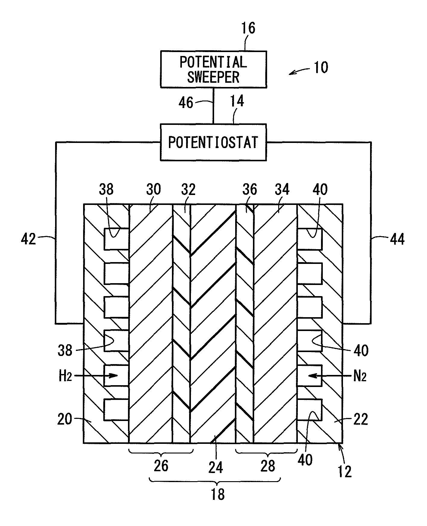
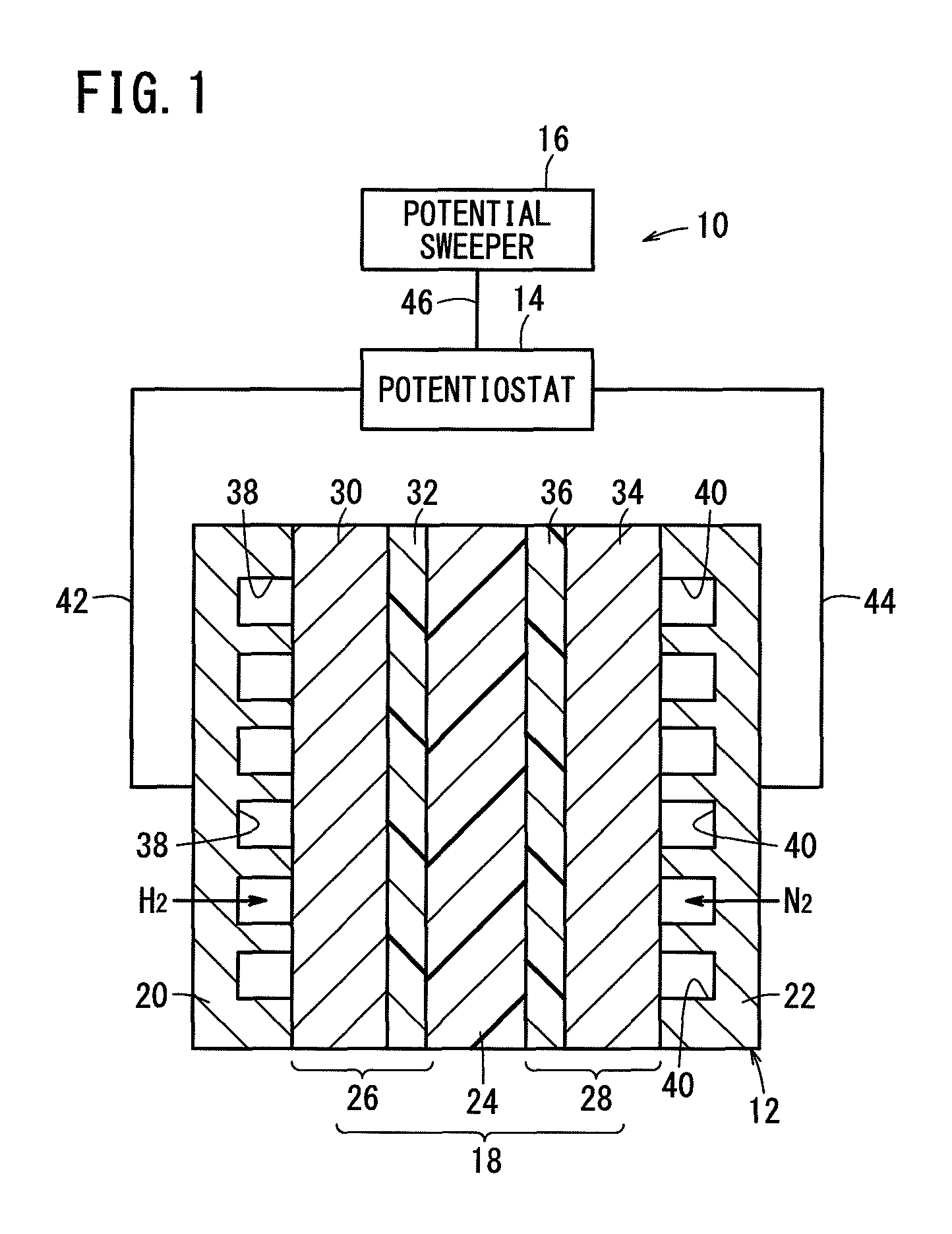
[0067]First, an activation apparatus 10 will be described below with reference to FIG. 1. The activation apparatus 10 has a potentiostat 14 electrically connected to a solid polymer electrolyte fuel cell (hereinafter referred to also simply as a fuel cell) 12, and further has a potential sweeper 16 for controlling the potentiostat 14.

[0068]FIG. 1 shows the fuel cell 12 as a unit cell. Specifically, the unit cell has a membrane-electrode assembly 18, and first and second separators 20 and 22 sandwiching the membrane-electrode assembly 18 therebetween.

[0069]The membrane-electrode assembly 18 includes an electrolyte membrane 24, and an anode 26 and a cathode 28 sandwiching the electrolyte membrane 24 therebetween. The electrolyte membrane 24 is a solid polymer membrane made of a proton-conductive polymer. Ex...


PUM

PropertyMeasurementUnit
voltageaaaaaaaaaa
chargeaaaaaaaaaa
current versus voltage relationshipaaaaaaaaaa

Abstract

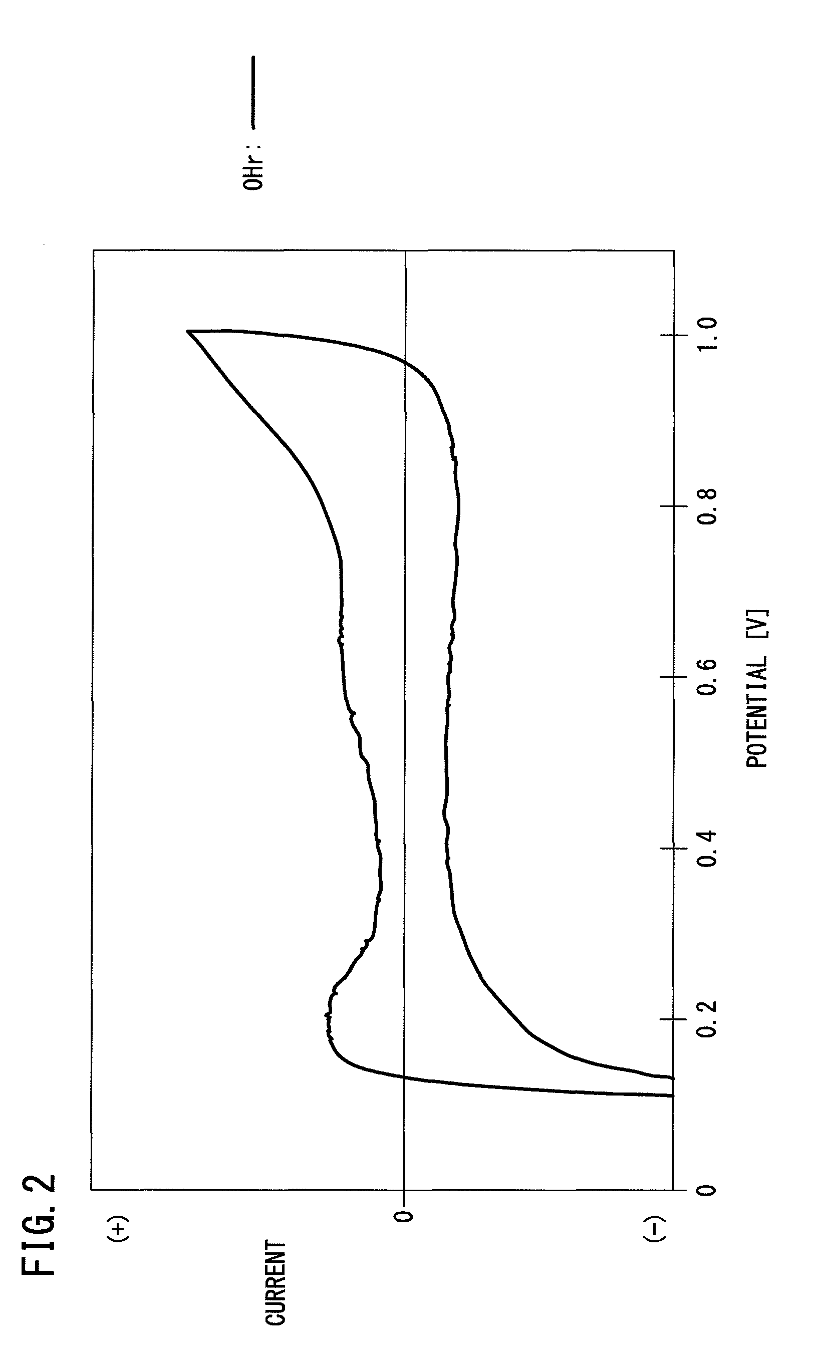
In a solid polymer electrolyte fuel cell, a potential is swept to obtain a cyclic voltammogram. The activation treatment is completed when any of conditions (a) to (c) is satisfied. (a): the peak number between 0.1 and 0.3 V increases from one to two, and inequalities of I1 / I3≧1.2 and I2 / I3≧1.2 are satisfied where I1, I2 and I3 are current values of the two peaks, and the minimum current value between the two peaks, respectively; (b): an oxidation peak within a range of 0.4 to 0.7 V decreases, and a charge amount corresponding to the peak decreases to 20 mC or less; and (c): the ratio I5 / I4 increases from less than 1 to 1 where I4 and I5 are current values of a reduction peak within a range of 0.6 to 0.7 V and a reduction peak within a range of 0.7 to 0.8 V, respectively.

Description

CROSS-REFERENCE TO RELATED APPLICATION[0001]This application is based upon and claims the benefit of priority from Japanese Patent Application No. 2011-287426 filed on Dec. 28, 2011, the contents of which are incorporated herein by reference.BACKGROUND OF THE INVENTION[0002]1. Field of the Invention[0003]The present invention relates to a method for activating a fuel cell having an electrolyte membrane containing a solid polymer, and more specifically to a method for activating a fuel cell, the method being capable of judging an activation completion timing.[0004]2. Description of the Related Art[0005]As is well known, a fuel cell having an electrolyte membrane containing a solid polymer is referred to as a solid polymer electrolyte fuel cell. The fuel cell contains a membrane-electrode assembly, which is formed by sandwiching the electrolyte membrane between an anode and a cathode.[0006]This type of the fuel cell is subjected to a treatment for achieving a sufficient power generati...

Claims


Application Information

Patent Timeline
Patent Type & Authority Patents(United States)
IPC IPC(8): H01M8/10H01M8/04
CPCH01M8/10H01M8/04223H01M8/04574H01M8/04873H01M2008/1095Y02E60/50H01M8/043H01M8/2457H01M8/04302
Inventor KATO, TAKASHITSUGE, HODAKAYAMADA, TADAAKI
Owner HONDA MOTOR CO LTD
Learn More