
Ventilation system for a passenger transit vehicle

a technology for transit vehicles and ventilation systems, which is applied in vehicle heating/cooling devices, transportation and packaging, railway bodies, etc., can solve the problems of detracting from passenger comfort, hot transit vehicles, and affecting passenger comfort, so as to avoid over-pressurization of passenger compartments

Active Publication Date: 2017-04-18
BOMBARDIER TRANSPORTATION GMBH
View PDF29 Cites 3 Cited by
  • Summary
  • Abstract
  • Description
  • Claims
  • Application Information

AI Technical Summary

Benefits of technology

The present invention is about a ventilation system for a passenger vehicle. It includes an air input system that brings in outside air from the vehicle's exterior and a exhaust system that expels air from the vehicle. This ensures that the vehicle does not become over-pressurized. The air is diffused in a way that provides each passenger with a consistent amount of air, and the system is designed to flow air at a speed of more than 0.15 meters per second. The technical effect of this invention is to provide a safe and effective way to ventilate passenger vehicles while in transit.

Problems solved by technology

When weather temperatures increase, transit vehicles can become hot, stuffy and suffocating, which can greatly detract from passenger comfort.
While air conditioning is effective at keeping temperatures within the transit vehicles comfortable, a deficiency with these systems is that they are expensive to purchase and to operate.
A deficiency with these ventilation systems is that they generally concentrate the supply of air in a given location, such that not all the passengers benefit from the farming effect.
A further deficiency with these existing ventilation systems is that the fan's ability to move air decreases as the vehicle accelerates.
Furthermore they do not adjust dynamically to increasing passenger discomfort.

Method used


Image

  • Ventilation system for a passenger transit vehicle
  • Ventilation system for a passenger transit vehicle
  • Ventilation system for a passenger transit vehicle

Examples


Embodiment Construction

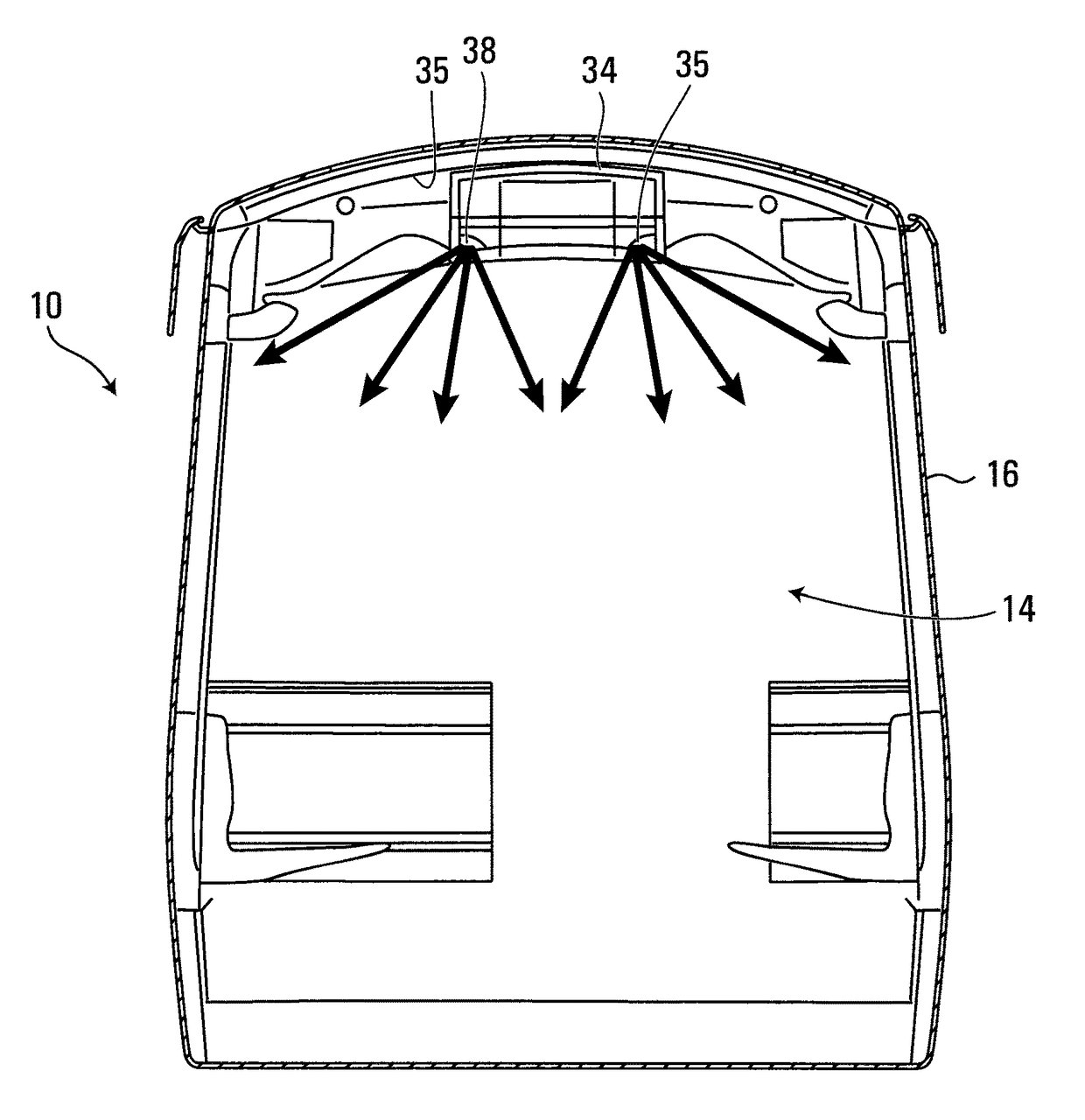
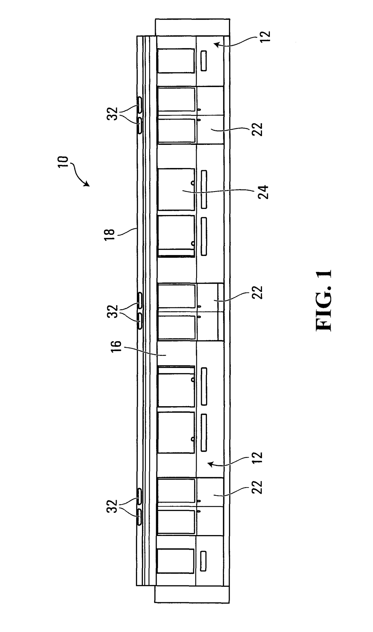
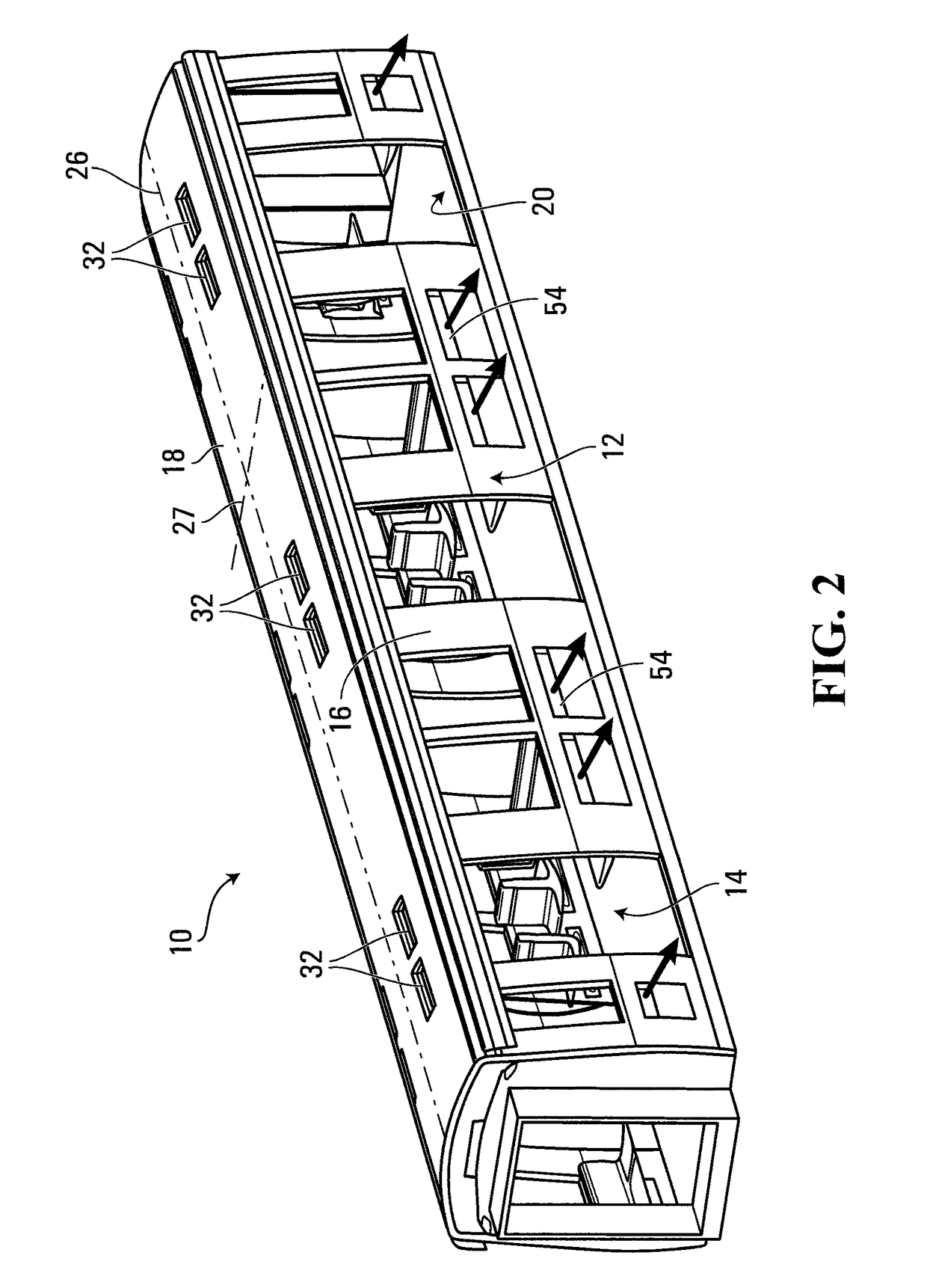
[0026]Shown in FIGS. 1 and 2 is a passenger transit vehicle 10 suitable for incorporating therein a ventilation system according to the present invention. In the non-limiting embodiment shown, the passenger transit vehicle 10 is in the form of a metro car. However, the ventilation system could be used in any type of passenger transit vehicle 10, such as an above-ground railway vehicle, a monorail car or a bus, among other possibilities. The ventilation system of the present invention is not limited to use within a specific type of passenger transit vehicle 10.

[0027]The passenger transit vehicle 10 shown in FIGS. 1 and 2 comprises an outer shell 12 that defines an interior passenger compartment 14 for receiving passengers. In the embodiment shown, the outer shell 12 comprises two side walls 16, a roof 18 and a floor 20. The two side walls 16 comprise doors 22 for allowing passengers to enter and exit the passenger compartment 14, and windows 24 for allowing the passengers to look out...


PUM


Abstract

A ventilation system for a passenger transit vehicle that comprises a passenger compartment. The ventilation system comprises a variable speed fan for providing outside air to the passenger compartment, wherein within a given ambient temperature range, the speed of the variable speed fan is controlled such that the air speed produced by the variable speed fan increases with increasing ambient temperature. The ventilation system further comprises a duct system fluidly connecting the variable speed fan to an air diffuser that directs the air from the variable speed fan towards the passengers within the passenger compartment. The cross sectional area of the duct system decreases along its length for providing substantially constant air pressure along its length. The ventilation system is able to provide outside air into the passenger compartment at an air flow speed of greater than 0.15 m / s.

Description

CROSS REFERENCE TO RELATED APPLICATIONS[0001]This application claims the benefit under 35 USC §119(e) of U.S. provisional patent application Ser. No. 61 / 439,717 filed on Feb. 4, 2011. The contents of the above-mentioned patent applications are incorporated herein by reference.FIELD OF THE INVENTION[0002]The present invention relates to the field of ventilation systems for passenger transit vehicles, and more particularly to ventilation systems that provide passenger comfort through the use of one or more variable speed fans that provide outside air to the interior of the passenger transit vehicle.BACKGROUND OF THE INVENTION[0003]Passenger comfort is an important consideration for any passenger transit vehicle. Much consideration is given to the suspension, the seating and the power delivery in order to ensure a smooth and comfortable ride for the passengers. However, when considering passenger comfort, another important criterion to take into consideration is the transit vehicle's v...

Claims


Application Information

Patent Timeline
Patent Type & Authority Patents(United States)
IPC IPC(8): B60H1/00B61D17/12B60H1/24B61D17/18B60H1/26B61D27/00
CPCB60H1/00828B60H1/00371B60H1/00735B60H1/00885B60H1/245B60H1/247B60H1/262B61D17/12B61D17/18B61D27/009
Inventor CHAGNON, MARCLANGLOIS, JACQUESMARSALA, JENNYBEAULLEU, RENE
Owner BOMBARDIER TRANSPORTATION GMBH
Learn More