
Traffic lane marking recognition apparatus and traffic lane marking recognition program

a technology of traffic lane marking and recognition apparatus, which is applied in the direction of instruments, computing, electric digital data processing, etc., can solve the problems of blurred white line, inconvenience for passengers, blurred white line, etc., and achieve the effect of suppressing the inability of driving assistance control resulting from erroneous recognition of lane dividing line upon entry into a tunnel

Active Publication Date: 2017-04-18
DENSO CORP
View PDF12 Cites 0 Cited by
  • Summary
  • Abstract
  • Description
  • Claims
  • Application Information

AI Technical Summary

Benefits of technology

The patent describes a system for recognizing traffic lanes based on images captured by a camera in a vehicle. The system detects lane dividing lines and gaps in the lines, and reduces the likelihood of mistakenly recognizing a gap as a lane dividing line. This improves the stability of traffic lane recognition and reduces unstable driving assistance control when entering tunnels.

Problems solved by technology

Therefore, for example, when lane keeping control is performed, steering is aimed towards a target that is shifted from the intended steering target, and passengers may experience discomfort.
The white line may become blurred even outside of a tunnel, and the above-described issue arises when the white line becomes blurred, regardless of whether the white line is inside or outside of a tunnel.
When only a lane dividing line on one side of a traffic lane is recognized, recognition may become more unstable than when the lane dividing lines on both sides of a traffic lane are recognized, because the recognition is dependent on the accuracy of recognition of the lane dividing line on one side.
Blurring of a lane dividing line inside a tunnel causes erroneous recognition of fluorescent portions of pole-shaped cones or the like as a white line.

Method used


Image

  • Traffic lane marking recognition apparatus and traffic lane marking recognition program
  • Traffic lane marking recognition apparatus and traffic lane marking recognition program
  • Traffic lane marking recognition apparatus and traffic lane marking recognition program

Examples


first embodiment

(First Embodiment)

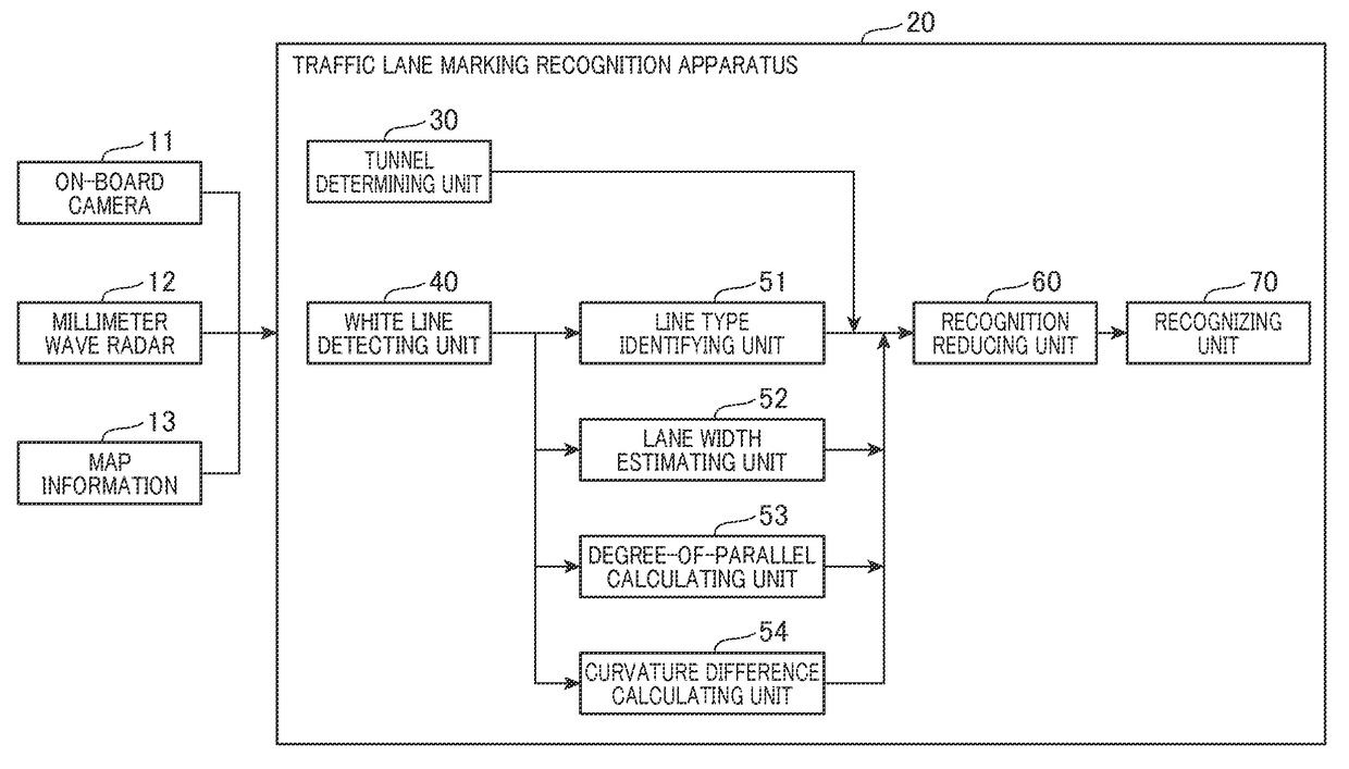
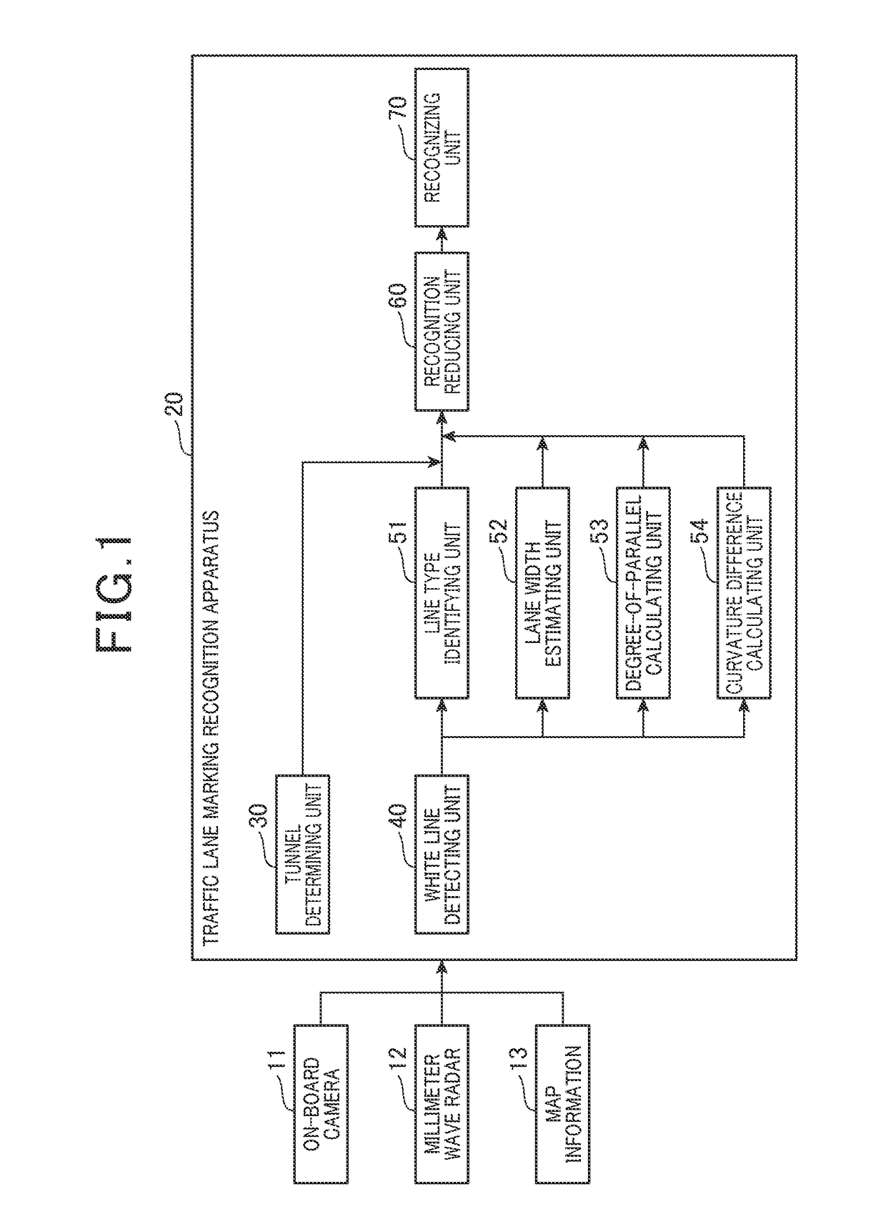
[0035]First, a configuration of a traffic lane marking recognition apparatus 20 according to the present embodiment will be described with reference to FIG. 1. The traffic lane marking recognition apparatus 20 according to the present embodiment is an on-board apparatus that recognizes white lines (corresponding to lane dividing lines or lane markings) that define traffic lanes on a road, using images captured by an on-board camera 11.

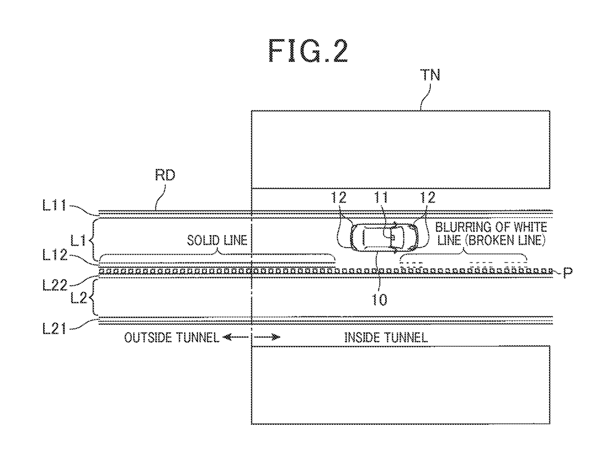
[0036]The on-board camera 11 is configured by at least one of a charge coupled device (CCD) camera, a complementary metal-oxide-semiconductor (CMOS) image sensor, a near infrared camera, and the like. As shown in FIG. 2, the on-board camera 11 is mounted in a vehicle 10 so as to capture images of the peripheral environment including the road ahead of the vehicle 10. Specifically, the on-board camera 11 is set near the upper end of the front windshield of the vehicle 10 and captures images of an area that spreads over a predetermined a...

second embodiment

(Second Embodiment)

[0096]A traffic lane marking recognition apparatus 20A according to a second embodiment differs from the traffic lane marking recognition apparatus 20 according to the first embodiment in terms of being able to recognize a portion of a detected white line candidate that can be regarded as a solid line even when a blurred white line candidate for a white line is detected, to improve stability of white line recognition. The white line herein refers to all lane dividing lines (lane markings) that define traffic lanes, including a yellow line. In the second embodiment, components or steps identical with or similar to those in the first embodiment are given the same reference numbers for the sake of omitting unnecessary explanation.

[0097]First, the differences from the traffic lane marking recognition apparatus 20 according to the first embodiment in the configuration of the traffic lane marking recognition apparatus 20A according to the second embodiment will be descr...

third embodiment

(Third Embodiment)

[0119]According to the second embodiment, no differentiation is made between when a white line that had originally been configured by a solid line has become blurred to include a gap, and when a white line has originally been configured by a broken line that includes a gap. When the white line candidate includes a gap, the probability of recognition of the white line candidate as a white line is uniformly reduced.

[0120]According to a third embodiment, when a white line that had originally been configured by a solid line has become blurred to include a gap, and when a white line has originally been configured by a broken line that includes a gap are differentiated. The probabilities of recognition of the white line candidate as a white line are set to differing values between these two cases. The differences from the second embodiment in the traffic lane marking recognition apparatus 20A according to the third embodiment will hereafter be described. In the third emb...


PUM


Abstract

A traffic lane marking recognition apparatus includes a candidate detecting unit, a gap detecting unit, and a recognition reducing unit. The candidate detecting unit detects a lane dividing line candidate which is a candidate for a lane dividing line that defines a traffic lane on a road, based on an image of the road captured by an on-board camera that is mounted in a vehicle. The gap detecting unit detects a gap included in the lane dividing line candidate detected by the candidate detecting unit. When the gap is detected by the gap detecting unit, the recognition reducing unit reduces a probability of recognition of the lane dividing line candidate as a lane dividing line to a first probability that is lower than the probability when the gap detecting unit does not detect the gap, in a region from the gap closest to the vehicle towards a direction away from the vehicle.

Description

CROSS-REFERENCE TO RELATED APPLICATION[0001]This application is based on and claims the benefit of priority from Japanese Patent Application Nos. 2014-150095, filed Jul. 23, 2014, and 2014-227240, filed Nov. 7, 2014, the disclosures of which are incorporated herein in its entirety by reference.BACKGROUND[0002][Technical Field][0003]The present invention relates to an apparatus that recognizes a lane dividing line (lane markings) such as a white line on a road, based on images from an on-board camera for driving assistance and the like of a vehicle, and a program thereof.[0004][Related Art][0005]An apparatus is proposed that recognizes a lane dividing line (lane markings) such as a white line on a road from images captured by an on-board camera and performs driving assistance and the like of a vehicle, based on the recognized lane dividing line on the road. In an apparatus such as this, appropriate recognition of the lane dividing line on the road even in a tunnel is desired.[0006]In...

Claims


Application Information

Patent Timeline
Patent Type & Authority Patents(United States)
IPC IPC(8): G06K9/00G06F19/00
CPCG06K9/00798G06V20/588
Inventor MAEDA, YUUSUZUKI, SHUNSUKEUEDA, YUSUKEISHIMARU, KAZUHISASHIMOMURA, OSAMUKAWASAKI, NAOKI
Owner DENSO CORP
Learn More