
Radiation image detecting device and radiation imaging system

a radiation image and detection device technology, applied in the field of radiation image detection devices and radiation imaging systems, can solve the problems of difficult cancellation of defects, position gaps between the grid and the dose measurement sensor, and difficult to place gaps in the geometric layout, so as to achieve the effect of little concern for deterioration of image quality

Active Publication Date: 2017-04-25
FUJIFILM CORP
View PDF3 Cites 10 Cited by
  • Summary
  • Abstract
  • Description
  • Claims
  • Application Information

AI Technical Summary

Benefits of technology

The present invention relates to a radiation image detecting device and a radiation imaging system. The invention provides a way to measure the radiation dose accurately without being affected by the position gaps between the sensor and the detection grid, which can cause image quality degradation. This is achieved by arranging the sensors with different intervals, so that they are never located at the maximum or minimum output value of the detection grid. This approach ensures stable AEC (automatic exposure control) without complex processes and reduces the risk of image quality degradation.

Problems solved by technology

Accordingly, production errors and installation backlash of the grid cause position gaps in the geometric layout with the grid and the dose measuring sensors.
Accordingly, production errors and installation backlash of the grid easily make position gaps between the grid and the dose measuring sensors, in the degree of about the width of one of the X-ray absorbing sections and the X-ray transmitting sections.
In addition, even in case that the type of the grid and imaging conditions are the same, since production errors and installation backlash of the grid cause position gaps in the geometric layout with the grid and the measuring pixels, the acquisition of gain image is carried out for every photography.
Furthermore, it is difficult to cancel the defect to the degree that the defect is not visible even if the defect correction is carried out, because the dose measuring sensor has the large size of approximately 50 mm.
Accordingly, there is a concern that the quality of the X-ray image will decrease.
This brings another problem that it should take time and require additional process for obtaining the gain image.
Furthermore, appropriate correction is not possible even if the acquired gain image is used, in case that position gaps in the geometric layout with the grid and the measuring pixels are occurred by a shock or other causes before performing the object photography after acquiring the gain image.

Method used


Image

  • Radiation image detecting device and radiation imaging system
  • Radiation image detecting device and radiation imaging system
  • Radiation image detecting device and radiation imaging system

Examples


first embodiment

[0060][First Embodiment]

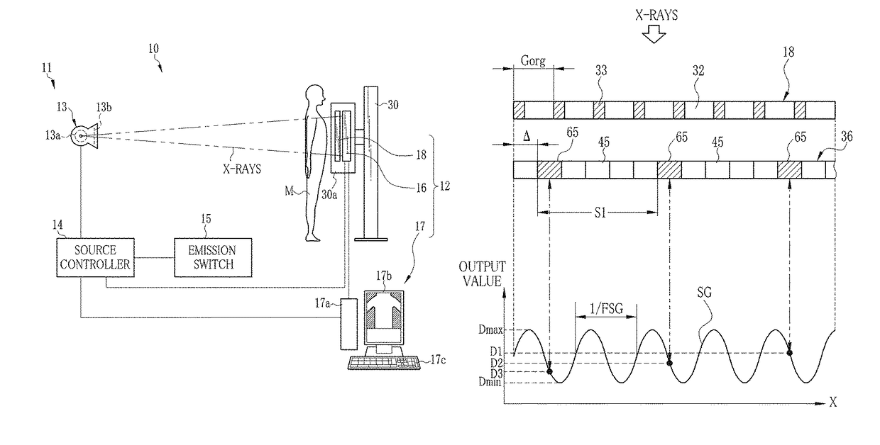
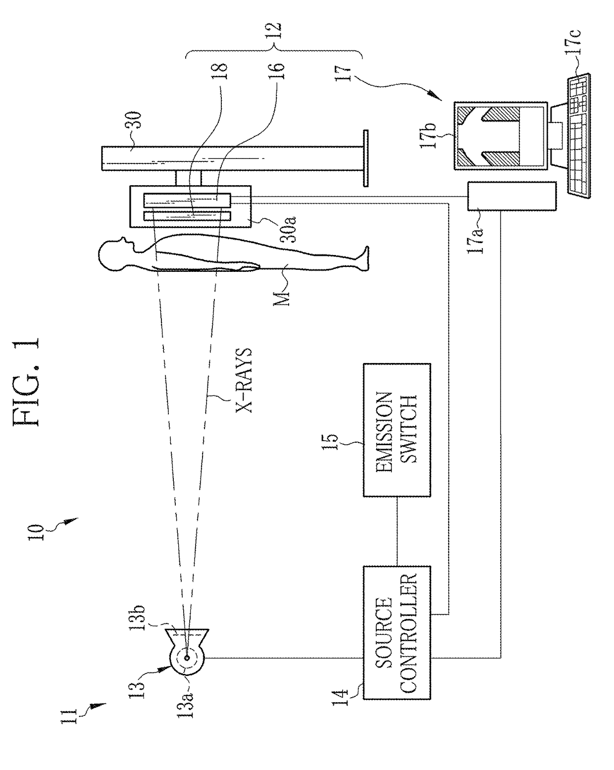
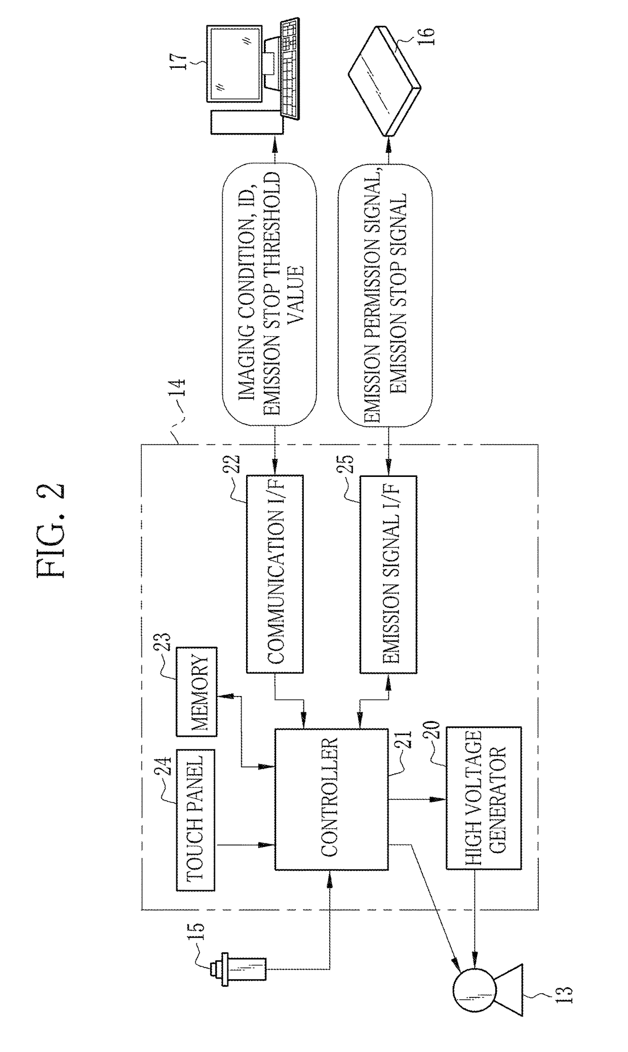
[0061]As shown in FIG. 1, an X-ray imaging system 10 is constituted of an X-ray generating device 11 for generating X-rays and an X-ray imaging device 12 for producing an X-ray image from the X-rays passed through a patient M (an object). The X-ray generating device 11 includes an X-ray source 13 for emitting X-rays, a source controller 14 for controlling the X-ray source 13, and an emission switch 15 for commanding the start of X-ray emission. The X-ray imaging device 12 includes an electronic cassette 16 which is a portable type X-ray image detecting device, a console 17 for controlling the electronic cassette 16, and an imaging stand 30. The source controller 14, the electronic cassette 16, and the console 17 are communicably connected to each other through a wired or wireless communication unit.

[0062]The electronic cassette 16 can be detachably attached to the imaging stand 30 which is in a standing position. The electronic cassette 16 includes an image d...

second embodiment

[0143

[0144]In FIG. 19, the arrangement period S1 becomes seven, because an interval corresponding to the six pixels 45 is provided between the two measuring pixels 65. The converted number by the conversion of the fluctuation period 1 / FSG of the grid detection signal SG into the number of the pixels 45 becomes four, because it has a length corresponding to the four pixels 45. Similarly, in an example illustrated in FIG. 20, the arrangement period S1 is six, and the fluctuation period 1 / FSG is four.

[0145]Both of FIG. 19 and FIG. 20 are the embodiments included in the present invention, because they satisfy the relation, the arrangement period S1≠the fluctuation period 1 / FSG. However, the example of FIG. 19 is more preferable than the example of FIG. 20. The reason is as follows. In the example of FIG. 19, the arrangement period S1 of the measuring pixels 65 is seven, and the fluctuation period 1 / FSG is four, so these two numbers are relatively prime. In contrast, in the example of FI...

third embodiment

[0151

[0152]In a third embodiment illustrated in FIGS. 21A to 23, an arrangement of groups of the measuring pixels 65 which calculate average value of dose measuring signals of the measuring pixels 65 is determined as one set 200, and the plurality of sets 200 are periodically arranged in the same row and other rows. In this way, the sets 200 are dispersed in the whole area of the imaging surface 36. The set 200 is the minimum unit of the group of measuring pixels 65 for calculating the average value of dose measuring signals of the measuring pixels 65 in the AEC section 67. Note that it is not necessary to arrange the sets 200 throughout the whole area of the imaging surface 36. For example, the sets 200 may be arranged intensively in a region corresponding to the predetermined measurement area such as a bilateral lung field.

[0153]In the example of FIG. 21A, the plurality of measuring pixels 65 (four in this example) are arranged in one line of the X2 direction, with the arrangement...


PUM

PropertyMeasurementUnit
sizeaaaaaaaaaa
lengthaaaaaaaaaa
lengthaaaaaaaaaa

Abstract

In a detection panel, plural pixels which receive X-ray and accumulate electric charge and plural measuring pixels which detect X-ray dose are provided on an imaging surface. The plural measuring pixels are arranged periodically with an interval. In a position facing to the imaging surface, there is a grid where X-ray absorbing sections and X-ray transmitting sections are arranged in a periodic alternating manner in a first direction. Since the arrangement period of the measuring pixels in the first direction is different from a fluctuation period of grid detection signals obtained when the grid is photographed by the detection panel, output values of the plurality of measuring pixels disperse and a fluctuation range of average values is suppressed.

Description

CROSS-REFERENCE TO RELATED APPLICATIONS[0001]This application is a Continuation of PCT International Application No. PCT / JP2013 / 060920 filed on Apr. 11, 2013, which claims priority under 35 U.S.C. §119 to Japanese Patent Application No. 2012-096276, filed Apr. 20, 2012. Each of the above application(s) is hereby expressly incorporated by reference, in its entirety, into the present application.BACKGROUND OF THE INVENTION[0002]1. Field of the Invention[0003]The present invention relates to a radiation image detecting device comprising a dose measuring sensor for an exposure control of a radiation image, and a radiation imaging system using this device.[0004]2. Description Related to the Prior Art[0005]In a medical field, an X-ray imaging system using radiation, e.g., X-ray is known. The X-ray imaging system comprises an X-ray generating device for generating X-ray and an X-ray imaging device for producing an X-ray image of an object (patient) with X-ray which penetrated the object. T...

Claims


Application Information

Patent Timeline
Patent Type & Authority Patents(United States)
IPC IPC(8): G01N23/04A61B6/00G01T1/08
CPCA61B6/542A61B6/4208A61B6/4291G01T1/08A61B6/4233A61B6/4283
Inventor TAJIMA, TAKASHIKUWABARA, TAKESHIKITAGAWA, YUSUKE
Owner FUJIFILM CORP
Learn More