Hip resurfacing drill guide device

a drill guide and hip technology, applied in the field of computer assisted surgery, can solve the problems of adding cost and time to the procedure, and the difficulty of intraoperative visualization of the femoral axis,

Active Publication Date: 2017-04-25
SYNVASIVE TECH
View PDF9 Cites 6 Cited by
  • Summary
  • Abstract
  • Description
  • Claims
  • Application Information

AI Technical Summary

Problems solved by technology

However, due to the limited exposure of the femoral head in minimally invasive surgery, femoral-axis alignment may be difficult to visualize intraoperatively.
Accordingly, radiographic instrumentation, such as a C-arm, is often required, and this adds costs and time to the procedure.

Method used


Image

  • Hip resurfacing drill guide device
  • Hip resurfacing drill guide device
  • Hip resurfacing drill guide device

Examples


Embodiment Construction

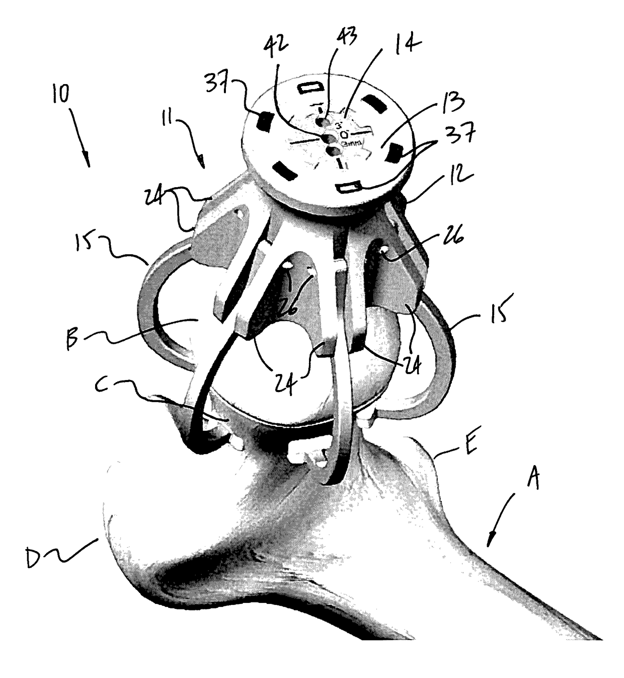
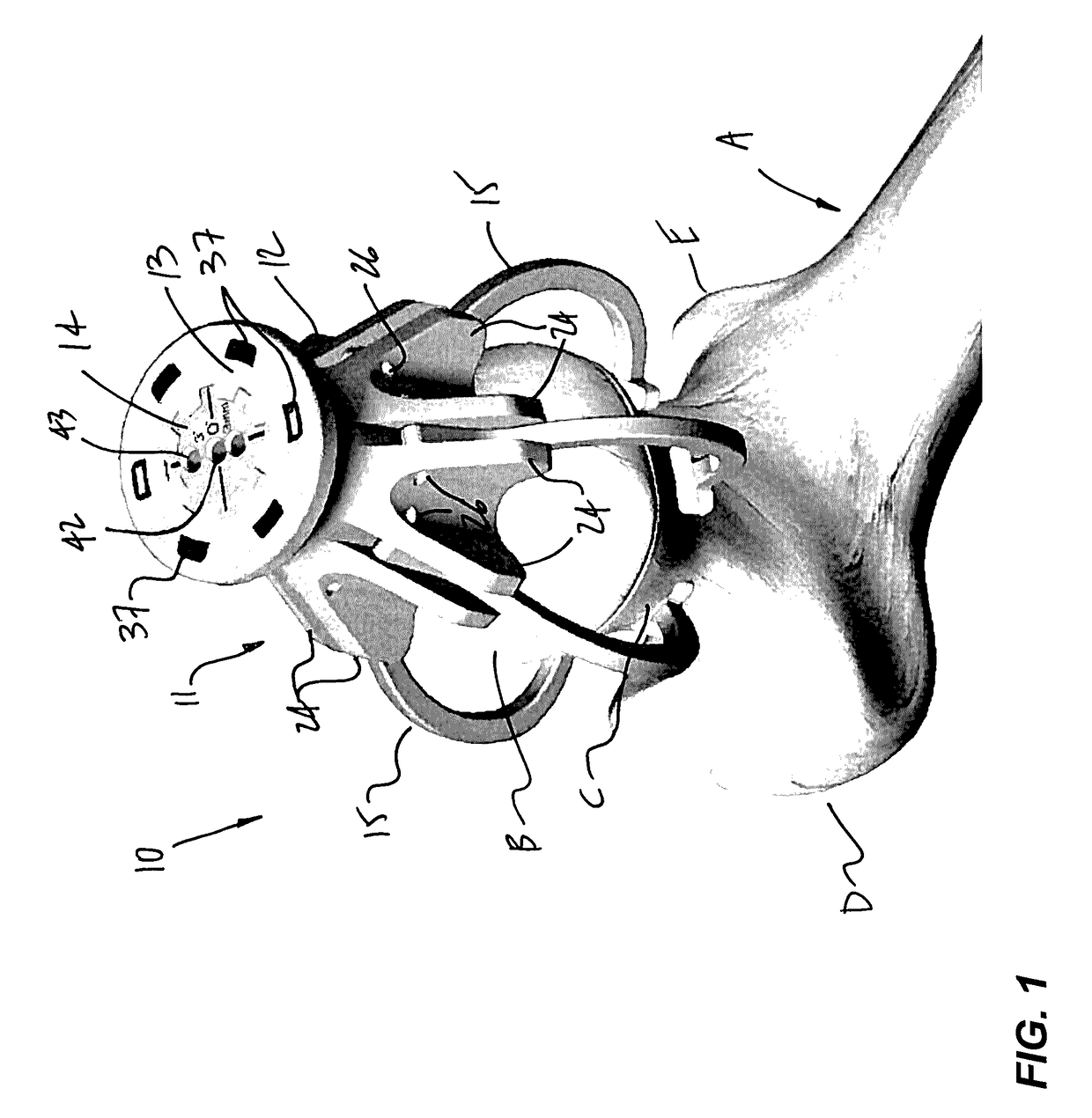
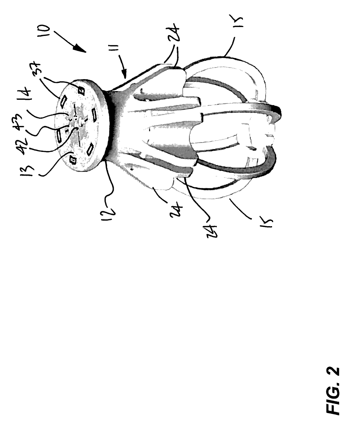
[0016]Referring to the drawings, and more particularly to FIG. 1, there is illustrated a hip resurfacing drill guide device 10 relative to the femur A. The femur A is shown prior to resurfacing, and has a femoral head B, a femoral neck C, a greater trochanter D and a lesser trochanter E, among other parts. The hip resurfacing drill guide device 10 is used to position a guide wire or pin into the femoral head, or to drill a guide hole in the femoral head B with a drill bit. The guide wire is then used as a guide for a cylindrical reamer, a cannulated drill or like resurfacing tool, used to remove bone from the femoral head, and hence shape same for subsequent positioning of a ball head implant on the resurfaced femoral head. The hip resurfacing drill guide device 10 is used to guide an operator in precisely and accurately positioning the guide wire in the femoral head B, which guide hole may extend into the femoral neck C as well. For simplicity, the device 10 will be referred to her...


PUM


Abstract

A device for guiding a drilling of a femoral head of a femur in femoral head resurfacing comprises a body defining a guide channel adapted to receive and guide a drilling component therein. Arms are pivotally connected to the body and biased toward one another, the arms each having a contact end extending below the body, the contact ends adapted to contact a femoral neck when the body is in a hovering position relative to the femoral head. Sensors produce a signal indicative of an orientation angle of each of the arms relative to the body. A processor unit calculates the orientation angles of the arms from the signal, and evaluates from the orientation angles an alignment of the body relative to the femur. A visual output produces a visual signal representative of said alignment. A method for aligning a drill guide device on a femur for subsequent drilling a femoral head with a guide channel in the drill guide device is also provided.

Description

TECHNICAL FIELD[0001]The present application relates to hip resurfacing in computer-assisted surgery.BACKGROUND OF THE ART[0002]Hip resurfacing consists in the implanting of a femoral head implant on a resurfaced femoral head, and the resurfacing of the acetabulum for the insertion therein of a cup implant. In such cases, the surgeon judges that the femoral neck is strong enough to remain unaltered, and the femoral head implant is used to replace damaged femoral head bone material. In comparison with total hip joint implanting surgery, the hip joint resurfacing surgery removes a relatively small amount of femoral bone while providing high levels of joint stability.[0003]Different output values are of concern in hip replacement surgery. In order to reproduce a natural and / or improved gait and range of motion to a patient, the position and orientation of the implants, the offset of the femur and the limb length must be considered during surgery. The work of the surgeon during hip repl...

Claims


Application Information

Patent Timeline
Patent Type & Authority Patents(United States)
IPC IPC(8): A61B17/17A61B17/56A61B90/00
CPCA61B17/1721A61B17/17A61B17/175A61B17/1739A61B17/1742A61B17/56A61B2017/564A61B2090/036A61B2090/0811A61B2017/00115
Inventor JOHANNABER, KENNETH DALE
Owner SYNVASIVE TECH
Why Eureka
Try Eureka