Advanced oxidation system and method in a UV reactor with electrode

a technology of oxidation system and electrode, which is applied in the direction of electrolysis components, water/sewage treatment by oxidation, water treatment compounds, etc., can solve the problems of reducing the uv dosage in the uv reactor, arc shortening, and blackening of the long-term pressure lamp, so as to achieve the effect of maximizing the surface area

Active Publication Date: 2017-04-25
NEPTUNE BENSON INC
View PDF10 Cites 3 Cited by
  • Summary
  • Abstract
  • Description
  • Claims
  • Application Information

AI Technical Summary

Benefits of technology

[0002]AOP that generally use UV plus peroxide can be used for many water and wastewater (i.e. fluid) based oxidation processes. Conventional peroxide systems are chemical based and generally require the dangerous chemical to be tankered in and stored. The present invention offers many advantages over what is done now.
[0004]In one embodiment, elongated, tubular UV lamps are used as the UV radiation source. Such lamps produce the least UV at their ends. In other words, the radiation intensity is diminished resulting in a lower UV dosage delivered near the lamp ends. Additionally, elongated medium pressure (MP) lamps blacken over time and the arc shortens. These characteristics result in diminished UV dosages in UV reactors having such lamps oriented transversely to the fluid flow. Accordingly, it would be advantageous to direct the flow of fluid away from the ends and towards the center of such elongated lamps. It is also advantageous to move the fluid away from the top & bottom of the chamber (i.e. vertically). The present invention overcomes these, as well as other disadvantageous that will be apparent to those of skill in the art, by tapering the electrode veins so as to direct the flow of fluid towards the center of the elongated lamps—the area of highest UV fluence.
[0008]One advantage of the L-shaped electrode of the present invention is to maximize surface area. The electrode is powered by DC voltage, and it has variable output base on the amperage and DC voltage that is fed to it. The DC voltage can switch, so as to assist in the removal of any scale of hardness from the electrode surface. In one embodiment, the voltage polarity (relative to the cathode and anode) is switched so as to assist in the removal of any scale of hardness from the electrode surface.H2O2+hν→2•OH Φ=1.0
[0023]The L-shaped electrode improves water flow patterns, which therefore improve the performance of the UV system.

Problems solved by technology

Conventional peroxide systems are chemical based and generally require the dangerous chemical to be tankered in and stored.
Additionally, elongated medium pressure (MP) lamps blacken over time and the arc shortens.
These characteristics result in diminished UV dosages in UV reactors having such lamps oriented transversely to the fluid flow.

Method used


Image

  • Advanced oxidation system and method in a UV reactor with electrode
  • Advanced oxidation system and method in a UV reactor with electrode
  • Advanced oxidation system and method in a UV reactor with electrode

Examples


Embodiment Construction

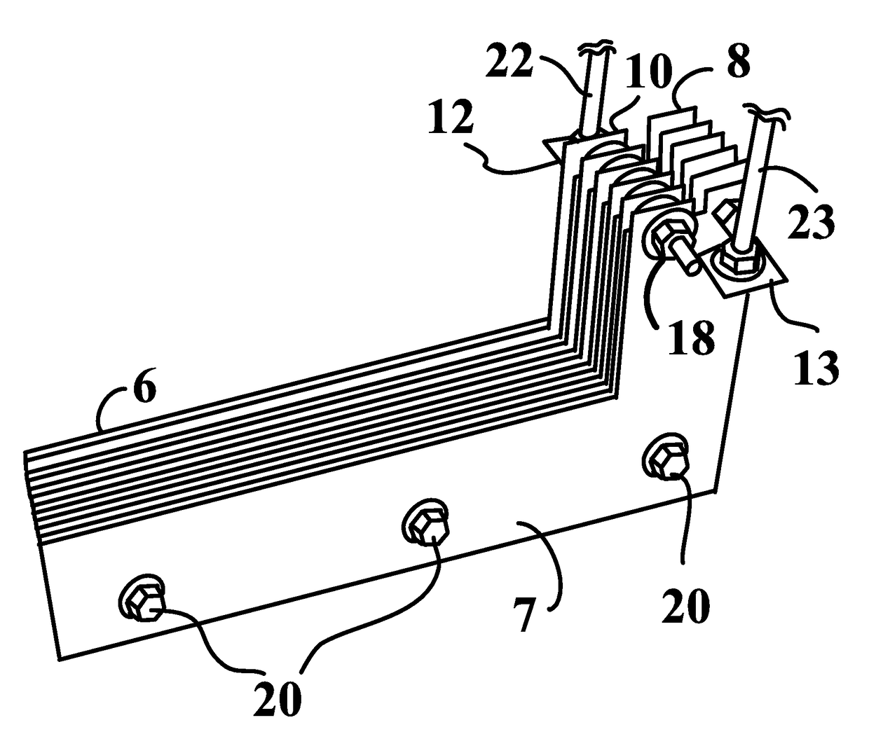
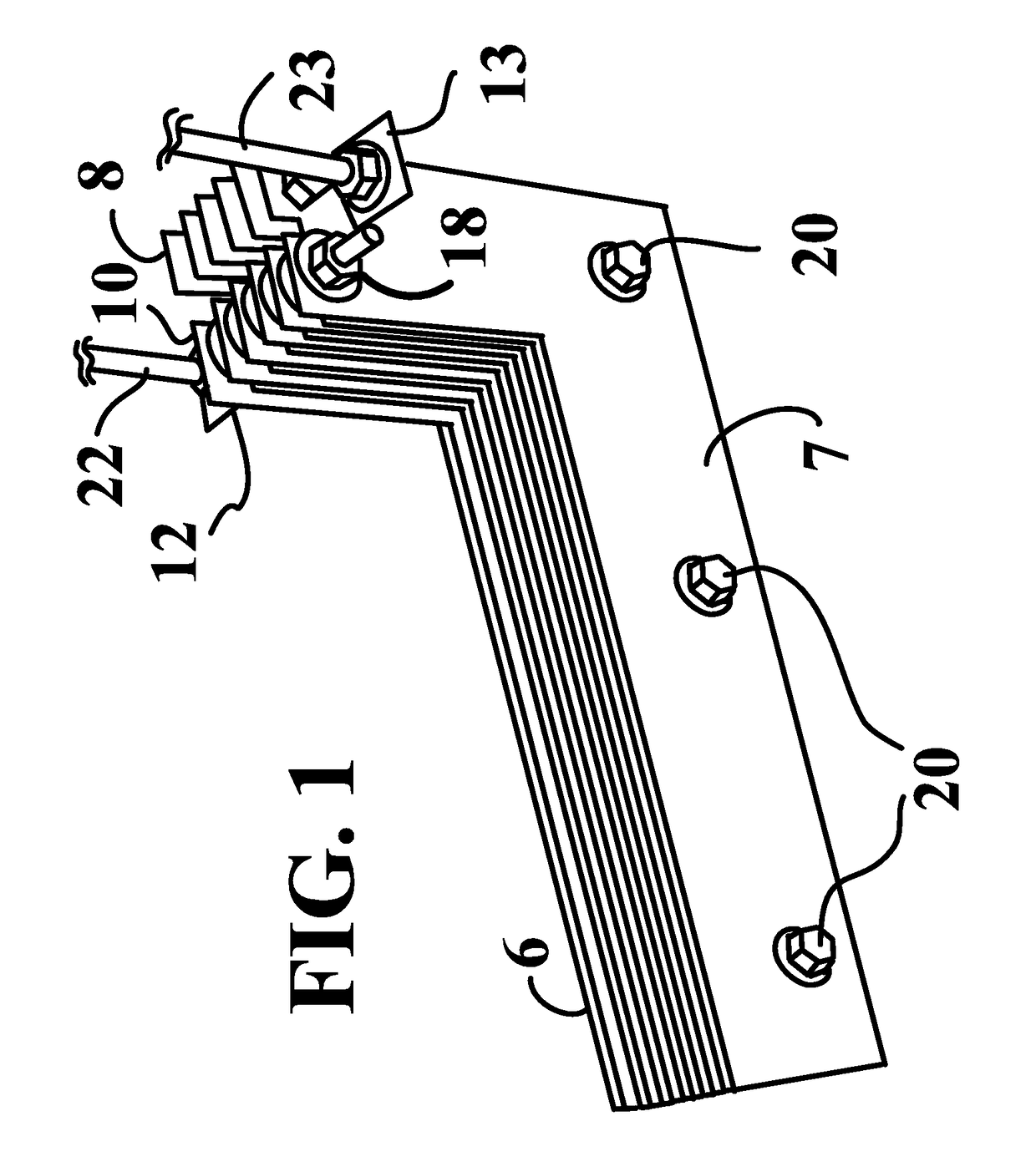
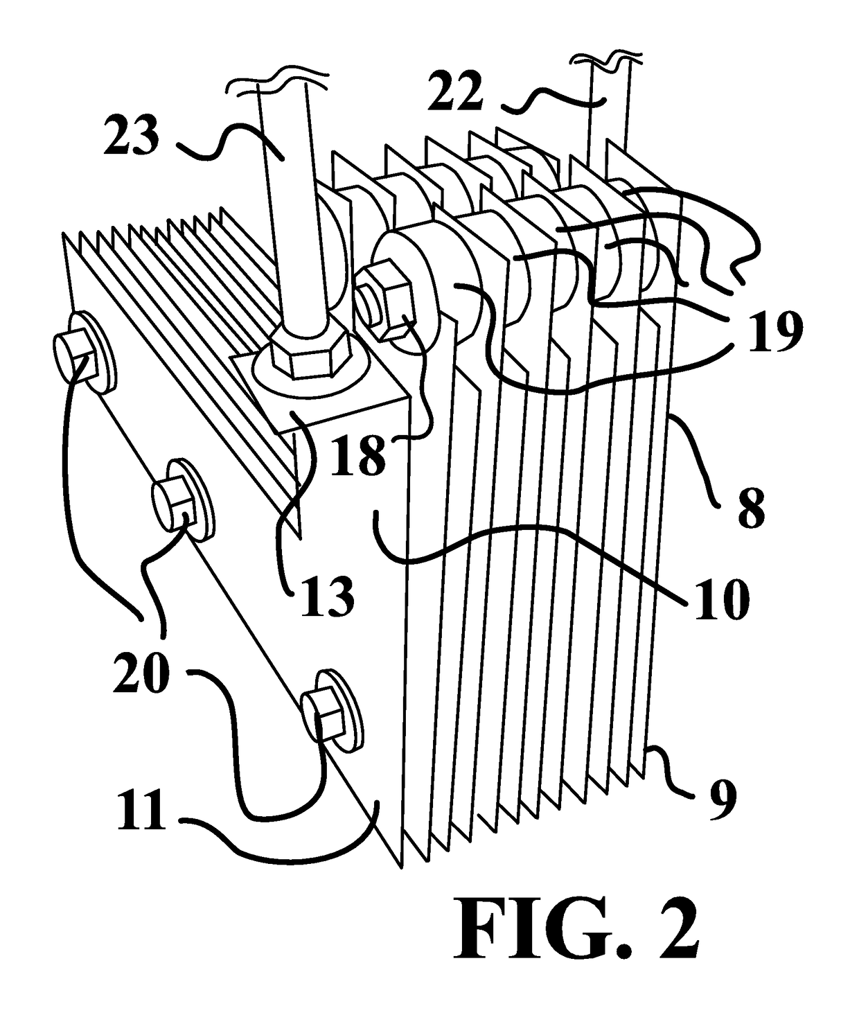
[0058]In one embodiment, in a UV (i.e. ultra violet) fluid reactor 1, an electrode 5 comprises, a plurality of L-shaped, substantially planar cathodes 6; and a plurality of L-shaped, substantially planar anodes 7.

[0059]In one embodiment, the UV radiation source comprises a plurality of tubular, medium pressure, mercury vapor lamps, enclosed by a quartz sleeve. Those of skill in the art will appreciate that other UV radiation sources can be used (e.g. amalgam lamps) without compromising the spirit of the invention.

[0060]The plurality of L-shaped, substantially planar cathodes 6 are electrically connected to each other and are at substantially a first voltage. The plurality of L-shaped, substantially planar anodes 7 are electrically connected to each other and are at substantially a second voltage. In one embodiment, the first and second voltages differ by approximately 36 volts (e.g. the first voltage is zero and the second voltage is 36 volts). In one embodiment, the range of DC vol...


PUM

PropertyMeasurementUnit
voltagesaaaaaaaaaa
voltageaaaaaaaaaa
DC voltageaaaaaaaaaa

Abstract

A system and method for applying an advanced oxidation process to a UV fluid reactor. An L-shaped electrode is connected to a UV reactor hatch and inserted into the reactor upstream from a UV radiation source.

Description

BACKGROUND AND SUMMARY[0001]The present invention relates generally to UV fluid treatment systems and specifically to such systems and methods that incorporate electrodes to facilitate advanced oxidation processes (AOP). Such electrodes include those that are based on electrolytic production of hydrogen peroxide, or are optimized for the production of hydrogen peroxide and / or for the destruction of organic contaminants in industrial wastewater, including mixed metal oxide electrodes having two kinds of metal oxides, such as those disclosed in U.S. Pat. No. 8,580,091 (issued Nov. 12, 2013), included herein by reference as if fully re-written herein.[0002]AOP that generally use UV plus peroxide can be used for many water and wastewater (i.e. fluid) based oxidation processes. Conventional peroxide systems are chemical based and generally require the dangerous chemical to be tankered in and stored. The present invention offers many advantages over what is done now.[0003]In one embodimen...

Claims


Application Information

Patent Timeline
Patent Type & Authority Patents(United States)
IPC IPC(8): C02F1/72C25B1/30C02F1/32C25B11/03C02F1/467C25B11/04C02F1/461C02F103/42
CPCC02F1/72C02F1/32C02F1/4672C25B1/30C25B11/035C25B11/0405C02F2001/46138C02F2001/46152C02F2103/42C02F2201/46105C02F2305/023C25B1/04C25B11/02C25B15/08C25B11/031C25B11/051Y02E60/36C02F1/46109C02F2001/46157
Inventor MCCLEAN, JONATHAN CHARLES
Owner NEPTUNE BENSON INC
Why Eureka
Try Eureka