Remote control transmitter

a transmitter and remote control technology, applied in the field of remote control transmitters, can solve the problems of not being able to achieve wide directivity in long distance areas, not being able to contribute to much improvement of operability of electric devices, and not being able to significantly so as to maintain the capability of long distance transmission, improve the operability, and widen the transmittable angle

Inactive Publication Date: 2009-02-17
FUNAI ELECTRIC CO LTD
View PDF12 Cites 10 Cited by
  • Summary
  • Abstract
  • Description
  • Claims
  • Application Information

AI Technical Summary

Benefits of technology

[0009]An object of the present invention is to provide a remote control transmitter which comprises plural light emitting diodes each as a light source for remote control, and which is widened in the transmittable angle and improved in the operability while maintaining its capability of long distance transmission.
[0011]This remote control transmitter is advantageous in that its transmittable angle can be widened with its capability of long distance transmission being maintained or without significantly reducing the radiation intensity at a central portion of the radiation range, thereby making it possible to improve the operability of the remote control transmitter.
[0013]Further preferably, the light emitting diodes emit infrared light, wherein the pair of light emitting diodes are placed side by side at a front end of the remote control transmitter, and wherein the maximum radiation directions of the pair of light emitting diodes are each inclined within a range no larger than 5 degrees outwardly of the remote control transmitter. The inclination of an infrared light emitting diode within a range no larger than 5 degrees does not cause a significant reduction in the radiation intensity. Accordingly, by placing the infrared light emitting diodes so as to be inclined symmetrically left and right and outwardly of the remote control transmitter each at an angle of 5 degrees, it becomes possible to widen the transmittable angle by 10 degrees without significantly reducing the radiation intensity in a central direction of the sum radiation range obtained by combining the radiation ranges of the pair of infrared light emitting diodes. Thus, the transmittable angle of the remote control transmitter can be widened while the capability of long distance transmission due to the use of the two light emitting diodes is maintained, thereby making it possible to improve the operability of the remote control transmitter.

Problems solved by technology

However, according to such conventional remote control transmitter 101, it has not been possible to significantly widen its transmittable angle although its capability of long distance transmission can be significantly improved by using the two light emitting diodes 111a and 111b.
However, it is not possible to obtain wide directivity in long distance areas.
In other words, such remote control transmitter may be suited to remotely control the door locking apparatus for cars, but cannot contribute to much improvement of operability of electric devices such as an image projector to be usually placed distantly from a user in a wide space.
However, it cannot extend the transmission distance.

Method used


Image

  • Remote control transmitter
  • Remote control transmitter
  • Remote control transmitter

Examples


Embodiment Construction

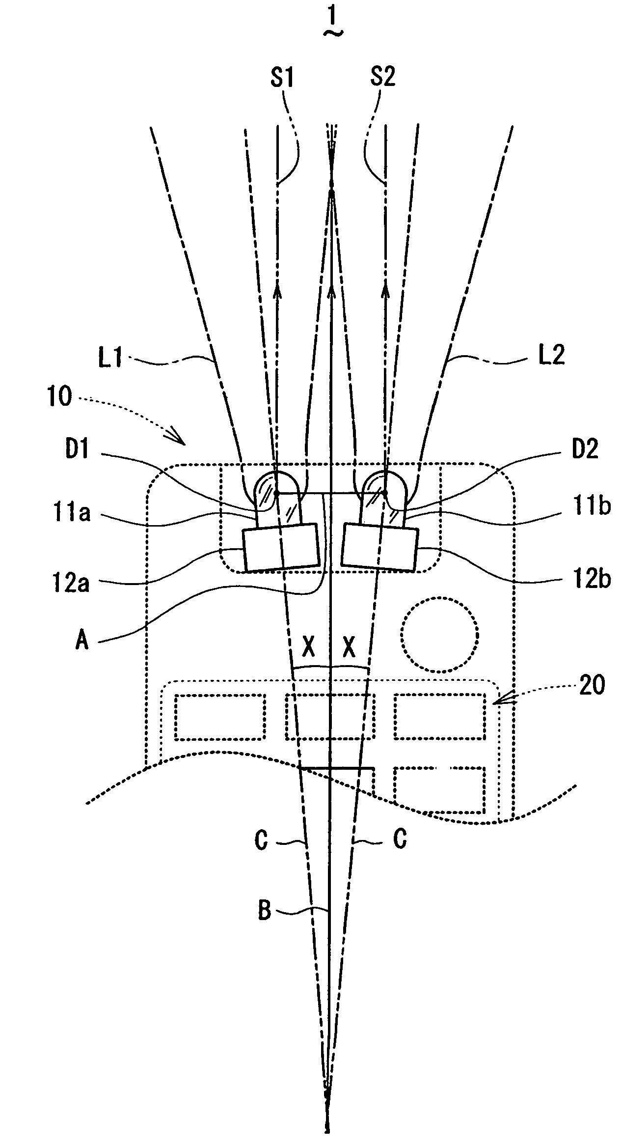
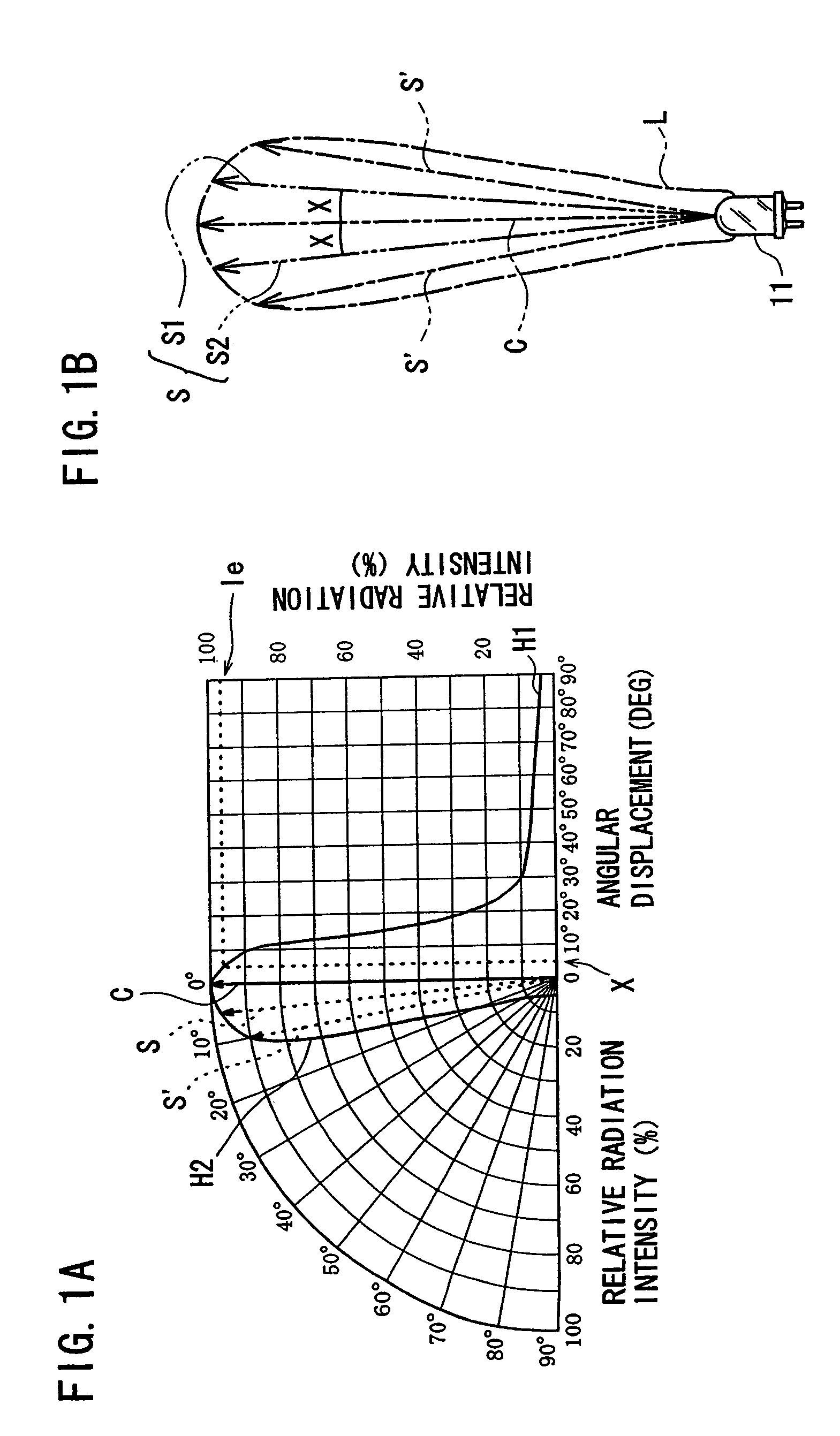
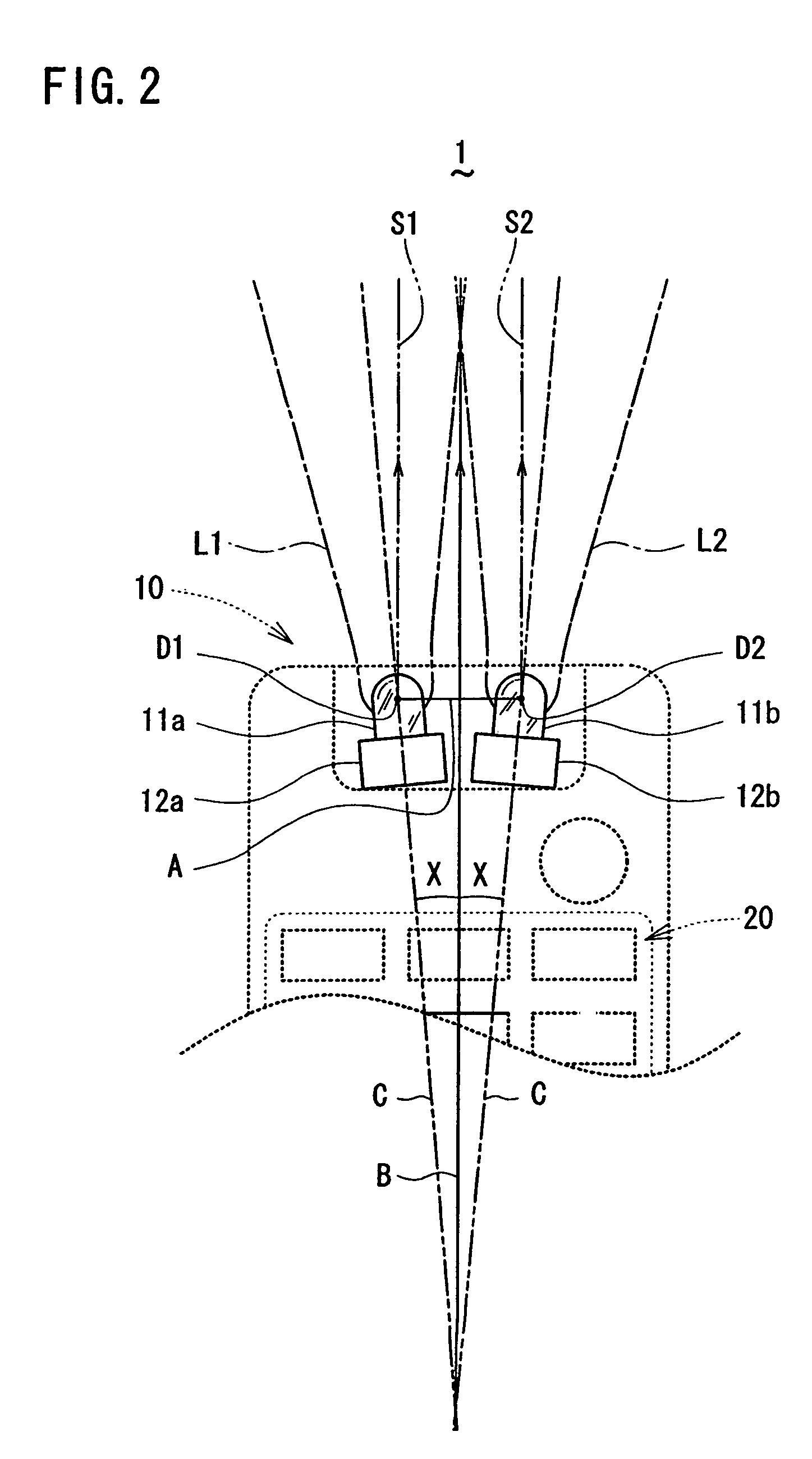
[0023]A remote control transmitter 1 according to a first embodiment of the present invention will be described hereinafter with reference to FIG. 1A, FIG. 1B and FIG. 2. This remote control transmitter 1 is of a type used to control electric devices such as an image projector to be used in a wide space. Two light emitting diodes 111 (11a and 11b) having a transmission range L as shown in FIG. 1B are used as light sources for remote control. Any light emitting diodes can be used therefor, but those emitting infrared light are used here.

[0024]Referring to FIG. 1A and FIG. 1B, the directivity of each light emitting diode 11 will be first described. In the right half of the graph of FIG. 1A, the horizontal axis indicates angular displacement, while the vertical axis indicates relative radiation intensity, in which the directivity characteristics of the light emitting diode 11 is shown by curve H1. On the other hand, the left half of the graph of FIG. 1A is a representation equivalent t...


PUM


Abstract

Light emitting diodes are placed side by side at a front end of the remote control transmitter in a manner that their maximum radiation directions, i.e. radiation directions each giving a maximum radiation intensity, are each inclined at an angle within a range no larger than 5 degrees outwardly of the remote control transmitter 1 and symmetrically with respect to a bisector of a line segment which connects center points of the light emitting diodes. The inclination, within a range no larger than 5 degrees, of each of the light emitting diodes used as light sources for remote control does not cause significant reduction in the radiation intensity. Accordingly, it is possible to widen the transmittable angle within a range no larger than 10 degrees without significantly reducing the radiation intensity at a central portion of the radiation range.

Description

BACKGROUND OF THE INVENTION[0001]1. Field of the Invention[0002]The present invention relates to a remote control transmitter to remotely control electric devices, and more particularly to a remote control transmitter suited to be used for an image projector.[0003]2. Description of the Related Art[0004]It is known to use a remote control transmitter to remotely control electric devices. A light emitting diode is used as a light source for remote control in the remote control transmitter. In some cases, the remote control transmitter is used to control an electric device such as image projector that is placed in a wide space and remotely controlled. The remote control transmitter for such use is required to have a long transmission distance and a wide transmittable angle (wide directivity). For this reason, as shown in FIG. 5A and FIG. 5B, a conventional remote control transmitter 101 has a pair of light emitting diodes 111a and 111b. The pair of light emitting diodes 111a and 111b h...

Claims


Application Information

Patent Timeline
Patent Type & Authority Patents(United States)
IPC IPC(8): H04B10/00G08C19/12G08C23/04H04B10/11H04B10/114H04B10/524H04L17/02H04N5/00H04Q9/00
CPCG08C23/04
Inventor KYOTO, TOMOAKI
Owner FUNAI ELECTRIC CO LTD
Why Eureka
Try Eureka