Seasonal thermal energy storage system

Inactive Publication Date: 2017-04-25
SUNSHINE KAIDI NEW ENERGY GROUP CO LTD
View PDF4 Cites 6 Cited by
  • Summary
  • Abstract
  • Description
  • Claims
  • Application Information

AI Technical Summary

Benefits of technology

The invention is a seasonal system for storing and using heat. It can be used in large and medium-sized cooling and heating projects. It helps to conserve energy and reduce emissions. The system consists of a seasonal energy storage device, a solar collector, a water supply device, and a user terminal. These components form a closed-loop cooling and heating system, which is highly efficient in energy saving.

Problems solved by technology

Conventional seasonal energy storage is limited to solar energy and the energy saving effect is poor.

Method used


Image

  • Seasonal thermal energy storage system
  • Seasonal thermal energy storage system
  • Seasonal thermal energy storage system

Examples


Embodiment Construction

[0023]For further illustrating the invention, experiments detailing a seasonal thermal energy storage system for heat supply and removal are described below with reference to FIGS. 1-3. It should be noted that the following examples are intended to describe and not to limit the invention.

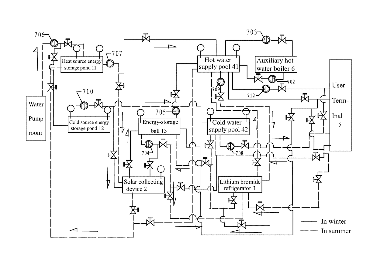
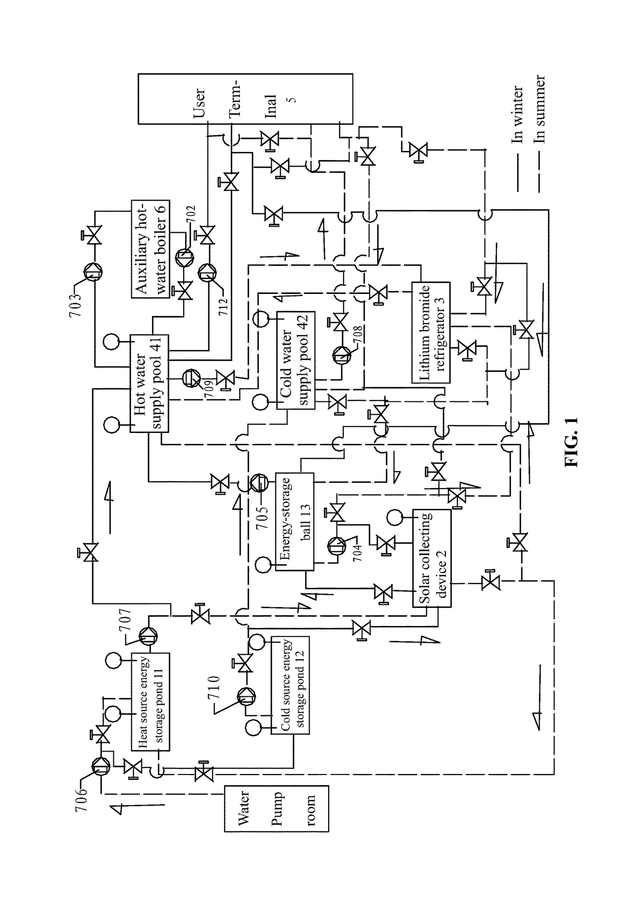
[0024]As shown in FIG. 1, a seasonal thermal energy storage system for heat supply and removal comprises an energy-storage device, a solar collector 2, a refrigerating unit 3, and a water supply device in closed-loop connection to a user terminal 5. The energy-storage device comprises at least a heat source storage pond 11 and a cold source storage pond 12, and the heat source storage pond 11 and the cold source storage pond 12 are connected to water source via first water pumps. The water supply device comprises a hot water supply pool 41 connected to the heat source storage pond 11 and a cold water supply pool 42 connected to the cold source storage pond 12. The solar collector is connected to the...


PUM


Abstract

A seasonal thermal energy storage system for heat supply and removal, including an energy-storage device, a solar collector, a refrigerating unit, and a water supply device in closed-loop connection to a user terminal. The energy-storage device includes at least a heat source storage pond and a cold source storage pond. The heat source storage pond and the cold source storage pond are connected to water source via first water pumps. The water supply device includes a hot water supply pool connected to the heat source storage pond and a cold water supply pool connected to the cold source storage pond. The solar collector is connected to the heat source storage pond and the hot water supply pool via second water pumps. The refrigerating unit is connected to the hot water supply pool and the cold water supply pool via third water pumps.

Description

CROSS-REFERENCE TO RELATED APPLICATIONS[0001]This application is a continuation-in-part of International Patent Application No. PCT / CN2012 / 083696 with an international filing date of Oct. 29, 2012, designating the United States, now pending, and further claims priority benefits to Chinese Patent Application No. 201110381778.8 filed Nov. 25, 2011. The contents of all of the aforementioned applications, including any intervening amendments thereto, are incorporated herein by reference.BACKGROUND OF THE INVENTION[0002]Field of the Invention[0003]The invention relates to the field of seasonal energy-storage, and more particularly to a seasonal thermal energy storage system.[0004]Description of the Related Art[0005]Conventional seasonal energy storage is limited to solar energy and the energy saving effect is poor.SUMMARY OF THE INVENTION[0006]In view of the above-described problems, it is one objective of the invention to provide a seasonal thermal energy storage system for heat supply ...

Claims


Application Information

Patent Timeline
IPC IPC(8): F25B27/00F24D11/00F24J2/34F24F5/00F25B30/04F25B15/06
CPCF24J2/345F25B27/007F24D11/003F24F5/0017F24F2005/0025F25B15/06F25B30/04Y02B10/20Y02B10/24Y02E60/147Y02E70/30F24S60/30Y02B30/62Y02E10/40Y02E60/14Y02P90/50Y02A30/27Y02A30/272
Inventor CHEN, YILONGHU, SHUCHUAN
Owner SUNSHINE KAIDI NEW ENERGY GROUP CO LTD
Why Eureka
Try Eureka