Jackable building foundation system

a technology of building foundations and jackable structures, applied in the field of building foundations, can solve the problems of not being able to build foundations for buildings above flood hazards, not being able to maintain a level platform, and being unable to meet the needs of building owners

Active Publication Date: 2017-05-09
HIGH TIDE HOMES
View PDF7 Cites 5 Cited by
  • Summary
  • Abstract
  • Description
  • Claims
  • Application Information

AI Technical Summary

Benefits of technology

[0005]The present invention comprises a steel beam support frame platform to which one or more platform jacks are attached. The platform jacks can be hydraulic jacks or electrically driven machine screw actuators, such as those of the Enerpac® M-Series. Vertical movement of the platform in response to jacking is constrained by cuboidal column guides at the four corners. Each of the column guides comprises two tiers of square roller frames, within each of which is an I-beam engaged between the flanges on either side by two rollers supported on horizontal axes. The orientations of the I-beams and rollers alternate orthogonally at each corner of the platform, so that torques generated by uneven jacking are suppressed and do not result in jamming of the platform as it rises.

Problems solved by technology

Construction of foundations for buildings above the flood hazard elevation is often not practical from a technical and / or economic standpoint.
Even where foundation construction above historic flood levels is feasible, the trend toward increasingly powerful storm surges and rising water in recent years poses a risk to any building in proximity to a body of water.
While designs for jackable building structures are known, the problem of maintaining a level platform under conditions of variable and / or unevenly-distributed lifting force has heretofore not been satisfactorily solved.

Method used


Image

  • Jackable building foundation system
  • Jackable building foundation system
  • Jackable building foundation system

Examples


Embodiment Construction

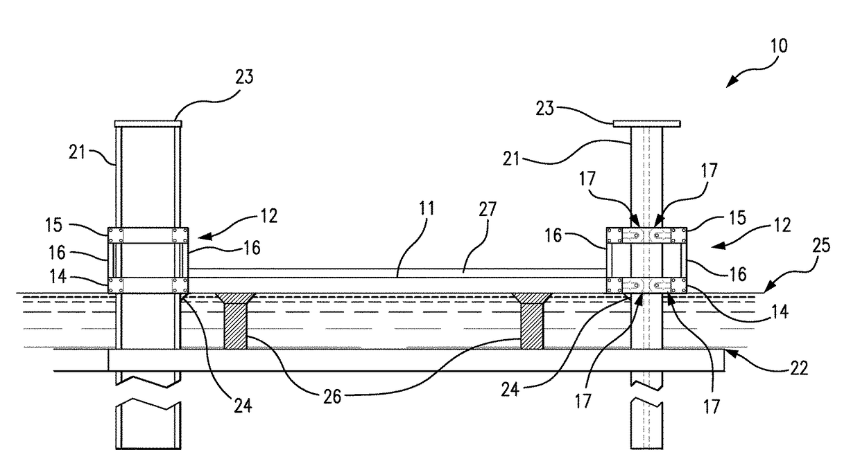
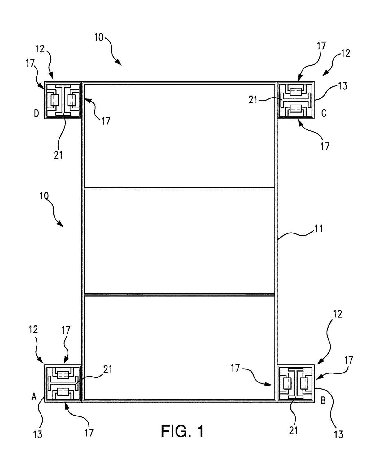
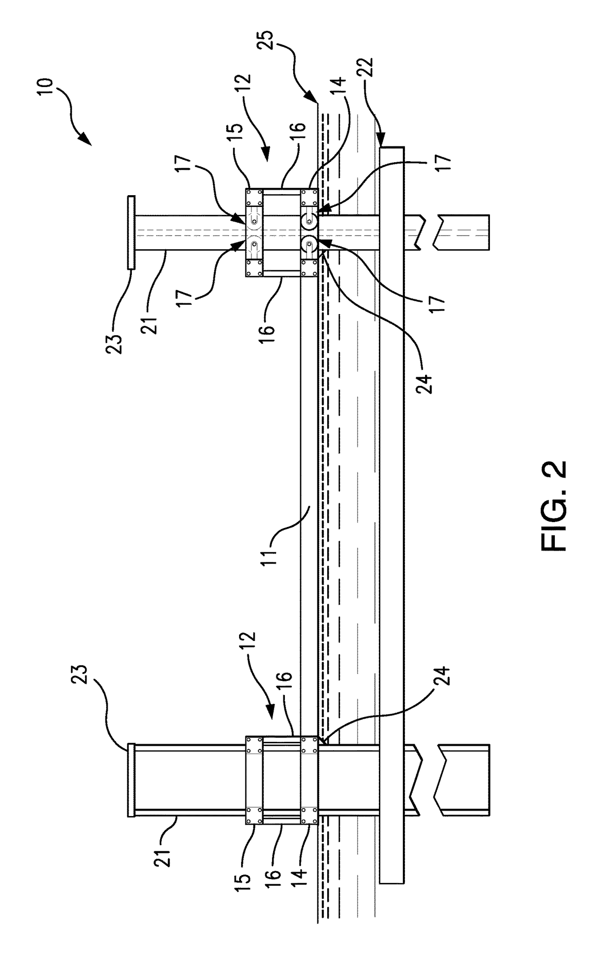
[0020]Referring to FIGS. 1 and 2, a jackable building foundation according to the preferred embodiment of the present invention 10 comprises a rectangular steel foundation support platform 11 with four cuboidal column guides 12, one at each corner. Each of the cuboidal column guides 12 comprises two interconnected square roller frames 13: a first tier roller frame 14 at the level of the foundation support platform 11, and a second tier roller frame 15 several feet above the level of the foundation support platform 11. The first and second tier roller frames 13 are rigidly interconnected at the corners by vertical members 16, so as to form an open cuboidal structure 12.

[0021]As best shown in FIG. 1 and in the detail view of FIG. 5, each roller frame 13 contains within it two roller mechanisms 17 on opposing sides on the roller frame 13. Each roller mechanism 17 comprises a cylindrical roller 18 having an axial bore 19, through which it is horizontally rotatably supported by a roller ...


PUM


Abstract

A jackable building foundation system includes a steel beam support frame platform to which one or more platform jacks are attached. Vertical movement of the platform in response to jacking is constrained by cuboidal column guides at the four corners. Each of the column guides comprises two tiers of square roller frames, within each of which is an I-beam engaged between the flanges on either side by two rollers supported on horizontal axes. The orientations of the I-beams and rollers alternate orthogonally at each corner of the platform, so that torques generated by uneven jacking are suppressed and do not result in jamming of the platform as it rises. The system is remotely controlled and monitored by a digital device, such as a smartphone, using application software.

Description

REFERENCE TO RELATED APPLICATION[0001]This application is a continuation-in-part of U.S. Utility patent application Ser. No. 15 / 097,709 filed on Apr. 13, 2016, which is incorporated herein by reference.FIELD OF INVENTION[0002]The present invention relates to the field of building foundations, and more particularly to elevated and jackable building foundations, the movement of which is constrained by guide columns.BACKGROUND OF THE INVENTION[0003]Buildings located in areas subject to the risk of damage and destruction from floodwaters associated with storm surges or rising water must either be elevated in place or removed from the floodplain in order to reduce flooding damage to them. Construction of foundations for buildings above the flood hazard elevation is often not practical from a technical and / or economic standpoint. Even where foundation construction above historic flood levels is feasible, the trend toward increasingly powerful storm surges and rising water in recent years ...

Claims


Application Information

Patent Timeline
Patent Type & Authority Patents(United States)
IPC IPC(8): E02B17/08E02D27/32E04H9/14E04B1/24E04G23/06E04B1/343
CPCE04B1/34336E04H9/145E04B1/24E04G23/065E02D27/32E02D2600/10E02D2200/11E04G21/163Y02A50/00
Inventor DESTEFANO, PHILIPBIANCO, JOHN A.
Owner HIGH TIDE HOMES
Why Eureka
Try Eureka