
Active transparent or translucent enclosures with energy control capacity

a transparent or translucent enclosure technology, applied in the field of building construction and climatization, can solve the problems of large building energy consumption, significant hydrostatic pressure, and large energy consumption in buildings, and achieve the effect of reducing thickness

Inactive Publication Date: 2010-02-25
UNIV MADRID POLITECNICA
View PDF33 Cites 6 Cited by
  • Summary
  • Abstract
  • Description
  • Claims
  • Application Information

AI Technical Summary

Benefits of technology

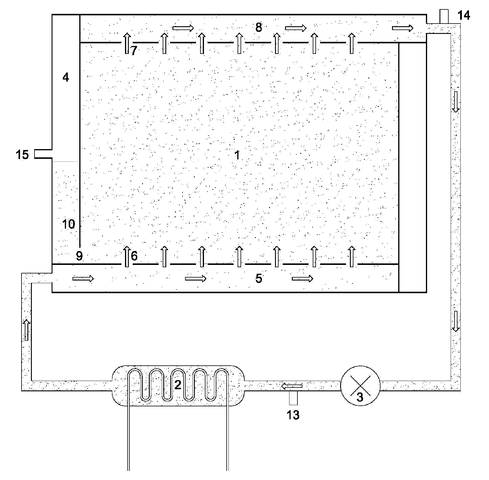
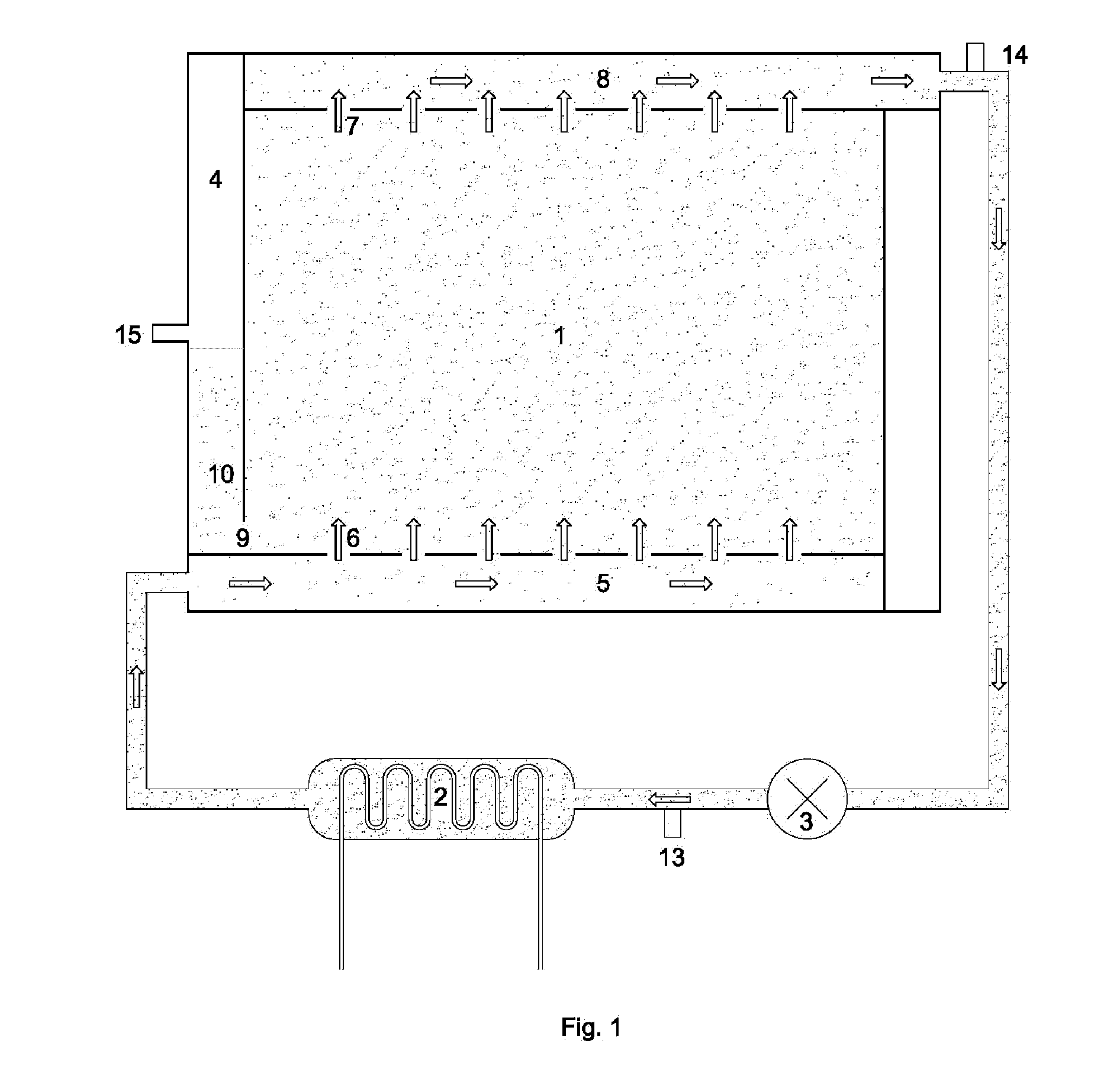
[0011]The active transparent enclosures with luminic and calorific energy management capabilities are characterized by the presence of a fluid, which manages the calorific energy through the convective transport of heat, and a dimming device in charge of controlling the illumination level. The active character of the enclosure is associated with its capability of controlling the incoming solar thermal load and illumination through an external regulation system. In order to accomplish the convective transport of heat with a chamber of reduced thickness, the fluid has to be a liquid. The hydrostatic pressure generated by the liquid in a vertical enclosure requires large thicknesses for the transparent panes, which renders the invention economically inviable.
[0014]In order to reduce the hydrostatic pressure in the closed circuit, and therefore, the thicknesses of the transparent panes, the very frame includes a hydrostatic pressure reducer device (4) connected to the chamber through a perforation (9). In this way, the hydrostatic pressure at the bottom of the chamber is regulated by the height of the liquid column (10), as shown in FIG. 4. The height of the liquid column is optimized such that the internal stresses of the transparent panes are minimal.
[0017]Thanks to the optimization process of the liquid column's height, an important reduction in the required thicknesses e to avoid the breakage of the panes is achieved. In order to understand this reduction it is convenient to remind that in a loaded plate one of its faces is compressed and the other one is stretched, being the latter the critical one. The maximum stresses present in the material depend on the thickness e and on the bending moments obtained from the solution to the problem. The present invention, with its process of minimizing the displacements w, minimizes also the acting bending moments, which translates into lower stresses in the transparent panes. Hence, given the breaking stress of the material, the present invention allows the use of thinner panes.
[0018]Another important characteristic of the load state result from the optimization process is that the net resulting force is zero, which translates into reduced reactions at the borders of the transparent pane. Again, given the breaking stress of the material employed for the peripheral sealing, the present invention allows the use of reduced depths in the peripheral sealing.
[0019]To better illustrate the advantages resulting from the optimization process of the liquid column's height, consider a 1 m width and 2 m height enclosure made out of glass panes, filled with water, and sealed with a silicone sealant. The present invention allows the reduction of the thickness of the glass panes from 25 mm to 12 mm, which translates into reduced costs and weight. Additionally, the depth of the peripheral sealing required to support the reactions can be reduced from 28 mm to 10 mm. Comparing with patent FR2176916 and employing in both cases the same glass pane thickness of 12 mm, the present invention allows to dismiss the three spacers required by the cited patent to avoid the breakage of the glass panes, which represents a significant advantage from the manufacturing and complexity points of view.

Problems solved by technology

The massive use of glass enclosures in contemporary architecture has originated large energy consumptions in buildings and an important reduction in comfort.
The low thermal insulation of the glass elements combined with their uncontrolled permeability to solar radiation are the reasons for their bad energetic behavior.
But the presence of the liquid in the interior of the enclosure leads to significant hydrostatic pressures which require the use of transparent panes with large thicknesses in order to avoid their breakage.

Method used


Image

  • Active transparent or translucent enclosures with energy control capacity
  • Active transparent or translucent enclosures with energy control capacity
  • Active transparent or translucent enclosures with energy control capacity

Examples


Embodiment Construction

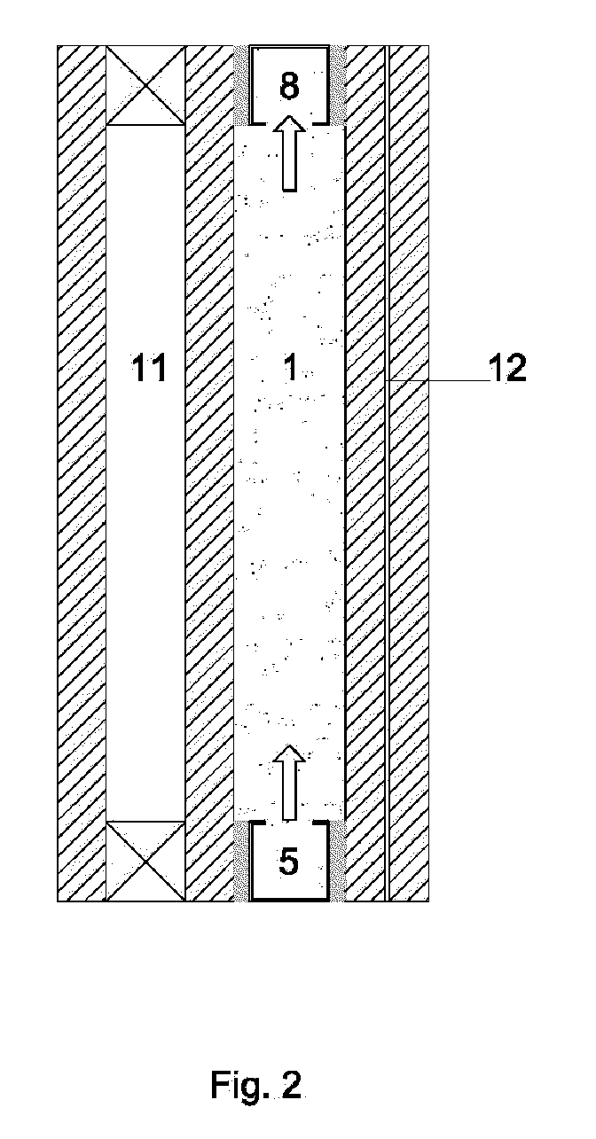
[0027]In order to present one embodiment, an enclosure for outer facades is considered. In this case, the system incorporates a double glass insulating unit with a gas chamber (11) which increases the insulating function and is in contact with the exterior. Instead, if the system is used as an interior partition, then the inclusion of the double glazing unit with gas chamber is not required, and both faces of the water chamber would act as radiating surfaces towards the interior of the building.

[0028]An aluminum frame is build out of rectangular hollow beams: the two horizontal beams form the distributor (5) and collector (8) and one of the vertical beams forms the hydrostatic pressure reducer device (4). Next, a double glazing unit is fixed on one of the sides of the frame and on the other side a laminated glass formed by two glass planes joined together with a Poly Vinyl Butyral layer (12). In the present embodiment a colored Butyral is chosen in order to statically control the il...


PUM


Abstract

An enclosure is made out of transparent or translucent panes which form a chamber (1) through which a liquid flows in closed circuit and which interchanges energy with the inner and outer environments, a heat exchanger (2) in contact with the liquid, a circulation pump (3), and a hydrostatic pressure reducer device (4). The hydrostatic pressure reducer device allows the reduction of the thicknesses of the transparent panes which hold the liquid inside. The active character of the enclosure is due to its capacity of controlling the solar heat load and the illumination. The solar heat load is regulated through the heat exchanger. The illumination of the building is controlled through the adjustable transparency of the liquid. The described enclosure allows the creation of an isothermal envelope which allows the climatization of the building. The system can be used for active outer enclosures or for interior partitions for the climatization and luminic control, as well as for glass roofs or false ceilings.

Description

[0001]This application is a Continuation-in-Part of PCT / ES2008 / 000071, filed 8 Feb. 2008, which claims benefit of Serial No. P200700476, filed 23 Feb. 2007 in Spain and which applications are incorporated herein by reference. To the extent appropriate, a claim of priority is made to each of the above disclosed applications.FIELD OF THE INVENTION[0002]The present invention belongs to the technical fields of building construction and climatization. Specifically, the application centers in transparent or translucent enclosures capable of controlling the outer and inner heat loads and the illumination of the building with the aim of achieving energy savings in climatization and improved comfort conditions.BACKGROUND OF THE INVENTION[0003]The massive use of glass enclosures in contemporary architecture has originated large energy consumptions in buildings and an important reduction in comfort. The low thermal insulation of the glass elements combined with their uncontrolled permeability ...

Claims


Application Information

Patent Timeline
IPC IPC(8): F24D3/12E06B7/00E04C2/54
CPCE06B3/6722E06B9/24Y02B10/20F24J2/0433F24J2/407E06B2009/2411F24S20/63F24S50/80
Inventor HERN NDEZ RAMOS, JUAN ANTONIOHERMANNS, MIGUELDEL AMA GONZALO, FERNANDOHERN NDEZ JIMENEZ, CESAR JAVIER
Owner UNIV MADRID POLITECNICA
Learn More