Internet protocol security camera connected light bulb/system
What is AI technical title?
AI technical title is built by Patsnap AI team. It summarizes the technical point description of the patent document.
a security camera and internet protocol technology, applied in the field of security cameras, can solve the problems of lack of signals from the light bulb, lack of solution, and limited control functions, and achieve the effect of cost-effective implementation
Active Publication Date: 2017-05-16
KUNA SYST
View PDF13 Cites 39 Cited by
Summary
Abstract
Description
Claims
Application Information
AI Technical Summary
This helps you quickly interpret patents by identifying the three key elements:
Problems solved by technology
Method used
Benefits of technology
Benefits of technology
[0008]The objects, features and advantages of the present invention include providing a security camera that may (i) receive power from a socket of an outdoor light, (ii) provide a wireless connection to a computer network, (iii) be cost effective to implement and / or (iv) provide intelligent control to a light bulb / system.
Problems solved by technology
Such systems do not have signals from the light bulb to the users to help the users decide how to control the light bulb.
Hence, the control functions would be limited to simple algorithms such as time-based on-off and random on-off timings.
Such systems do not provide any solution if there is no electrical outlet.
Often times, especially in an outdoor installation, electrical outlets are not available.
Adding a new electrical outlet for a residential home or a small business can cost more in time and money than an average cost of security camera hardware.
Disadvantages with conventional systems are significant.
A simple light bulb with one way communication cannot be intelligent.
Another disadvantage of conventional security cameras is that they do not provide a solution when there is no power outlet.
Method used
Image
Click on the blue label to locate the original text in one second.
Reading with bidirectional positioning of images and text.
Examples
Embodiment Construction
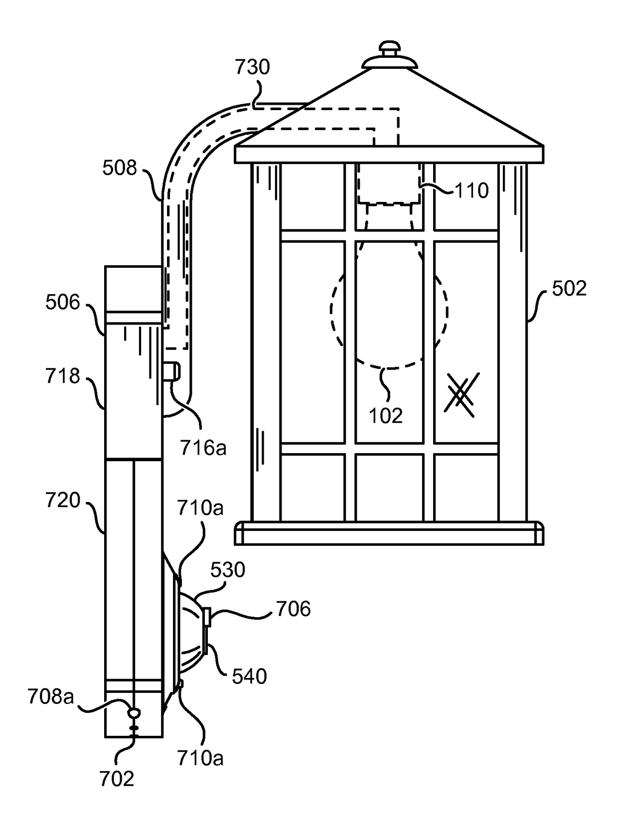
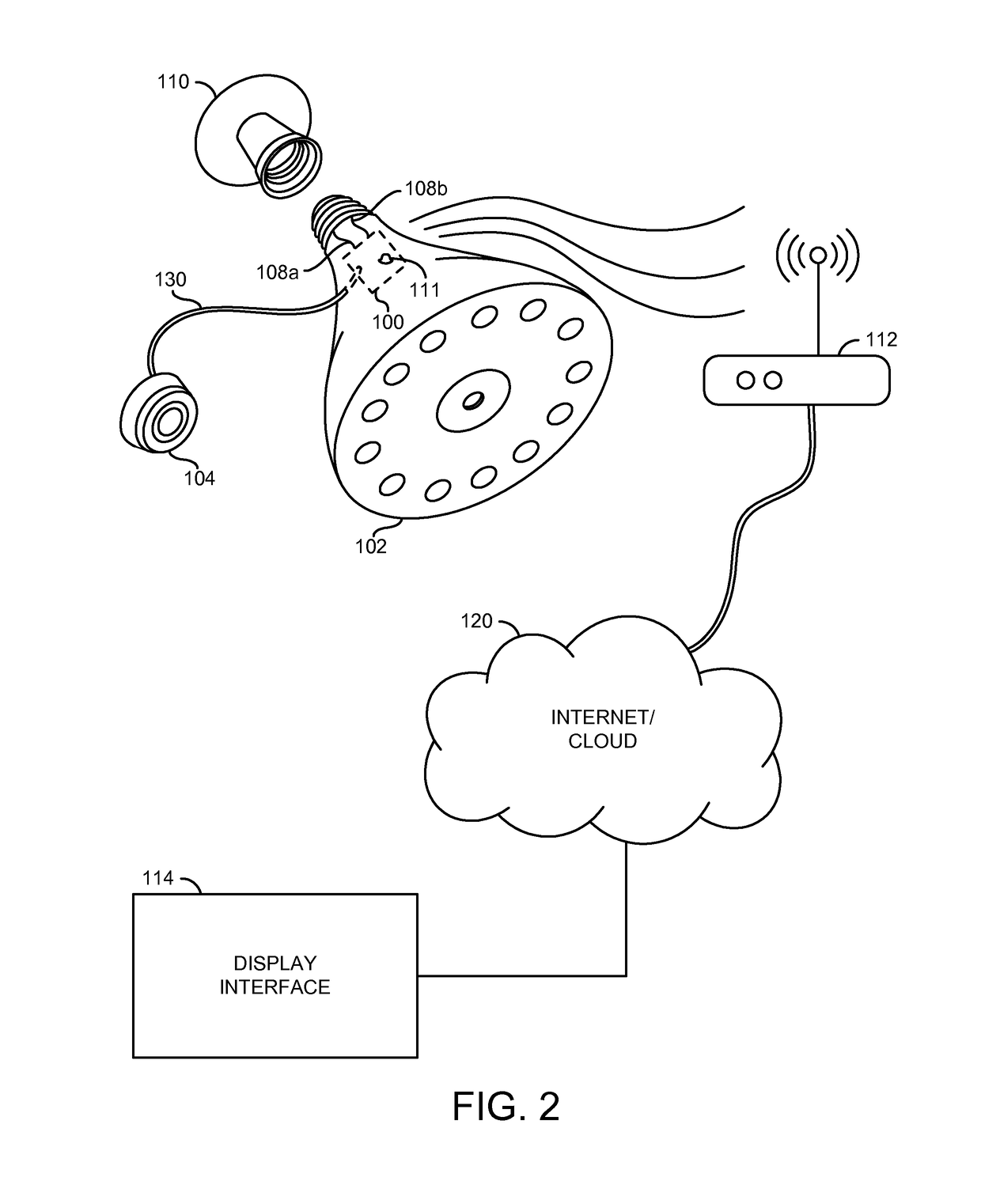
[0044]Referring to FIG. 1, a block diagram of a system 50 is shown in accordance with a preferred embodiment of the present invention. The system 50 generally comprises a camera module and sensor (with or without a lens) 100, a bulb 102, a lens module 104, an optional battery 106 (since DC power is provided from the light bulb), a number of detachable power and / or control wires 108a-108b, a bendable and rigid pipe (to provide structural support of 100 and 104), a light bulb socket for all popular bases 110, an antenna 111, a Wi-Fi adapter / router 112, a phone, tablet, PC, or TV display interface 114, and a cloud storage and / or computation / analytic of images 120. The cloud storage 120 may be the Internet, a local area network, a Network Attached Storage (NAS) device, etc.
[0045]The connection between the lens sensor 104 and the camera 100 may be implemented as a number of wires (a standard interface for lens module to cell phone circuitry) that may run at high bandwidth, and usually ve...
PUM
Abstract
The present invention concerns an apparatus comprising a shade, a camera sensor and a base. The camera sensor may be configured to capture video data of a surrounding environment of the apparatus. The base may be configured to enclose a circuit. The circuit may be configured to provide (i) an electrical connection to (a) the camera sensor and (b) components of the circuit, (ii) a connection between a power source and an external device, and (iii) control signals for activation of (a) the external device and (b) the components of the circuit. The circuit comprises an antenna module configured to connect and send data to a network through a wireless connection. The video data is sent as the data through the wireless connection. The camera sensor is positioned in a bottom part of the base that extends below the shade.
Description
[0001]This application relates to U.S. Ser. No. 14 / 164,540, filed Jan. 27, 2014, which relates to U.S. Ser. No. 13 / 921,597, filed Jun. 19, 2013, which relates to (i) U.S. Provisional Application No. 61 / 790,865, filed Mar. 15, 2013, (ii) U.S. Provisional Application No. 61 / 783,474, filed Mar. 14, 2013, and (iii) U.S. Provisional Application No. 61 / 684,310, filed Aug. 17, 2012. U.S. Ser. No. 14 / 164,540, filed Jan. 27, 2014 also relates to U.S. Provisional Application No. 61 / 923,931, filed Jan. 6, 2014. This application also relates to U.S. Ser. No. 14 / 205,946, filed Mar. 12, 2014, which relates to U.S. Provisional Application No. 61 / 783,565, filed Mar. 14, 2013. This application also relates to U.S. Ser. No. 14 / 519,642, filed Oct. 21, 2014, which relates to U.S. Provisional Application No. 61 / 902,943, filed Nov. 12, 2013. This application also relates to U.S. Ser. No. 14 / 504,632, filed Oct. 2, 2014. This application also relates to U.S. application Ser. No. 14 / 664,275, filed Mar. 20, ...
Claims
Application Information
Patent Timeline
Application Date:The date an application was filed.
Publication Date:The date a patent or application was officially published.
First Publication Date:The earliest publication date of a patent with the same application number.
Issue Date:Publication date of the patent grant document.
PCT Entry Date:The Entry date of PCT National Phase.
Estimated Expiry Date:The statutory expiry date of a patent right according to the Patent Law, and it is the longest term of protection that the patent right can achieve without the termination of the patent right due to other reasons(Term extension factor has been taken into account ).
Invalid Date:Actual expiry date is based on effective date or publication date of legal transaction data of invalid patent.

