Strategy for control of recirculated exhaust gas to null turbocharger boost error

a turbocharger and boost error technology, applied in the direction of electric control, machines/engines, mechanical equipment, etc., can solve the problems of unfavorable engine/vehicle performance, slow response characteristics of mechanical devices controlled by the control system, etc., to reduce nox formation, quick response, and increase the mass flow rate of exhaust gas

Inactive Publication Date: 2008-04-03
INT ENGINE INTPROP CO LLC
View PDF13 Cites 41 Cited by
  • Summary
  • Abstract
  • Description
  • Claims
  • Application Information

AI Technical Summary

Benefits of technology

[0018]When less boost is needed, the EGR valve will be promptly operated in its opening direction to quickly increase the mass flow rate of exhaust gas through the EGR valve so that more exhaust gas is i...

Problems solved by technology

While a processor-based engine control system can rapidly process data, mechanical devices controlled by the control system may have slower response charac...

Method used


Image

  • Strategy for control of recirculated exhaust gas to null turbocharger boost error
  • Strategy for control of recirculated exhaust gas to null turbocharger boost error
  • Strategy for control of recirculated exhaust gas to null turbocharger boost error

Examples


Embodiment Construction

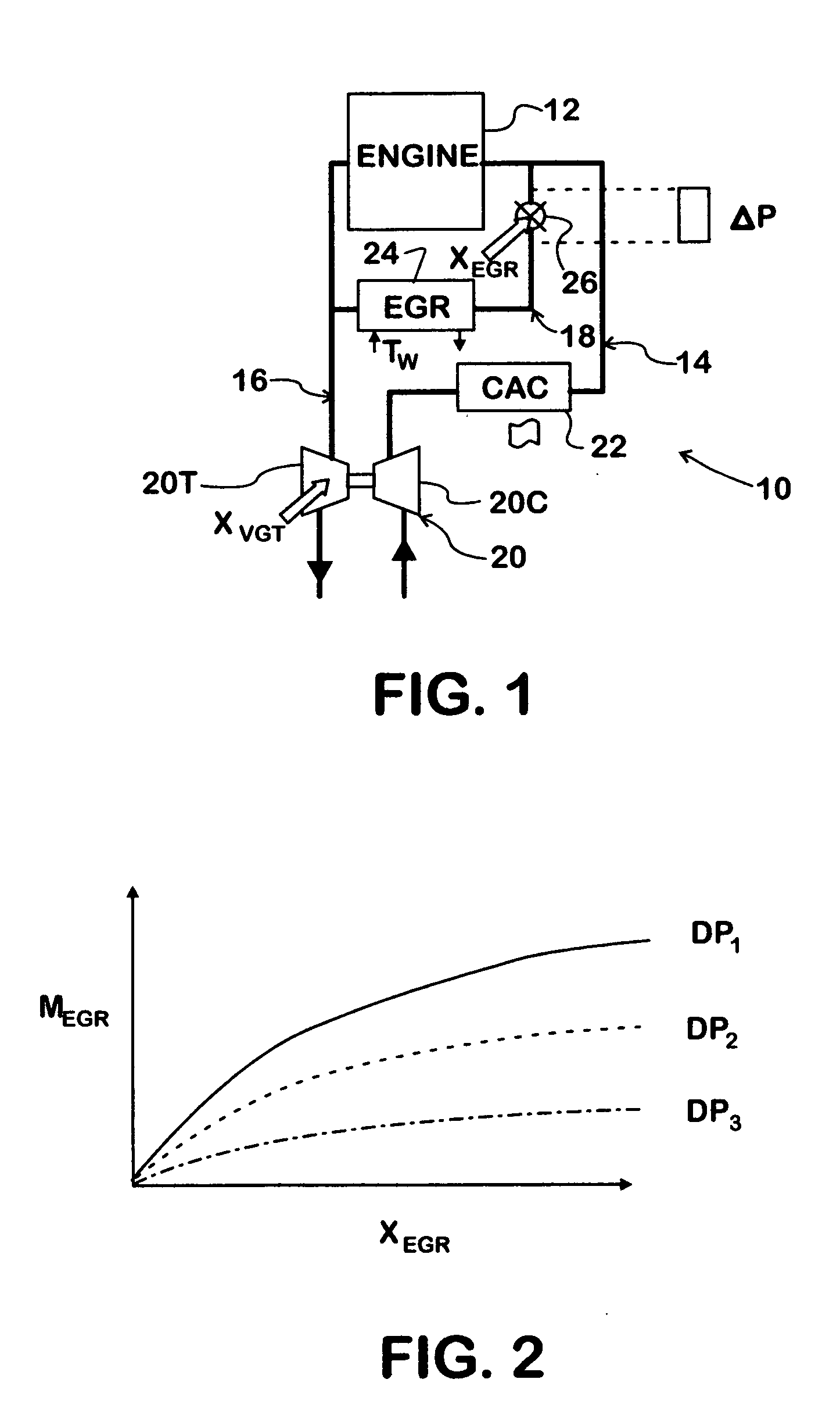
[0031]FIG. 1 shows an exemplary internal combustion engine system 10 comprising an engine 12 containing cylinders in which combustion occurs, an intake system 14 through which charge air can enter engine 12 and an exhaust system 16 through which exhaust gasses resulting from combustion of air-fuel mixtures in the cylinders exit. An EGR system 18 provides for exhaust gas to be recirculated from exhaust system 16 to intake system 14.

[0032]Engine system 10 is representative of a turbocharged diesel engine comprising a turbocharger 20 that has turbine 20T in exhaust system 16 operating a compressor 20C in intake system 14. A charge air cooler 22 is downstream of compressor 20C.

[0033]EGR system 18 comprises an EGR cooler 26 through which exhaust gas passes before reaching an EGR valve 26 that is controlled by a duty-cycle signal applied to an electric actuator of the valve to set the extent to which the EGR valve is open.

[0034]The inventive strategy is embodied in one or more processors ...


PUM


Abstract

A method for coordinating control of exhaust gas recirculation (18) in a turbocharged internal combustion engine (10) with control of engine boost. When actual boost deviates from a desired boost set-point developed by a boost control strategy (32), such as during a sudden acceleration or deceleration, the EGR control strategy (34) provides a prompt adjustment of exhaust gas recirculation (EGR) seeking to null out the boost disparity.

Description

FIELD OF THE INVENTION [0001]This invention relates to turbocharged internal combustion engines, particularly a motor vehicle diesel engine that in addition to having a turbocharger for developing boost has exhaust gas recirculation control.BACKGROUND OF THE INVENTION [0002]Turbocharged diesel engines are powerplants of many trucks that are presently being manufactured in North America, with single- and two-stage turbochargers being representative of those used. A two-stage turbocharger comprises high- and low-pressure turbines in series flow relationship in the exhaust system that operate high- and low-pressure compressors in series flow relationship in the intake system to develop boost is one example of a turbocharger. A single-stage stage turbocharger has only a single turbine and a single compressor.[0003]The high-pressure turbine of a particular type of two-stage turbocharger has vanes that can be controlled by an actuator to control both torque that operates the high-pressure...

Claims


Application Information

Patent Timeline
IPC IPC(8): F02B33/44
CPCF02B29/0406F02B37/00F02D21/08F02D23/00F02D41/0007F02D41/0072Y02T10/47F02D2041/141F02M25/0707F02M25/0727F02M25/0754F02M25/0772Y02T10/144F02D2041/1409F02M26/05F02M26/23F02M26/47F02M26/53Y02T10/12Y02T10/40
Inventor DE OJEDA, WILLIAM
Owner INT ENGINE INTPROP CO LLC
Why Eureka
Try Eureka