Flat pipe and heat exchanger

A flat tube and heat exchanger technology, applied in the field of heat exchangers, can solve the problems of low heat exchanger efficiency and insufficient heat exchange performance of flat tubes, and achieve uniform enthalpy difference, uniform outlet state, and uniform outlet specific enthalpy. Effect

Inactive Publication Date: 2009-09-09
SANHUA(HANGZHOU) MICRO CHANNEL HEAT EXCHANGER CO LTD
View PDF0 Cites 22 Cited by
  • Summary
  • Abstract
  • Description
  • Claims
  • Application Information

AI Technical Summary

Problems solved by technology

[0013] The purpose of the present invention is to provide a flat tube to solve the problem that the heat exchange performance of the flat tube in the prior art is not fully exerted and the efficiency of the heat exchanger is low

Method used


Image

  • Flat pipe and heat exchanger
  • Flat pipe and heat exchanger
  • Flat pipe and heat exchanger

Examples


Embodiment Construction

[0035] The purpose of the present invention is to provide a flat tube to solve the problems of insufficient heat exchange performance of the flat tube and low efficiency of the heat exchanger in the prior art.

[0036] The content of the present invention will be described below in conjunction with the accompanying drawings. The following description is only exemplary and explanatory, and should not have any limiting effect on the protection scope of the present invention.

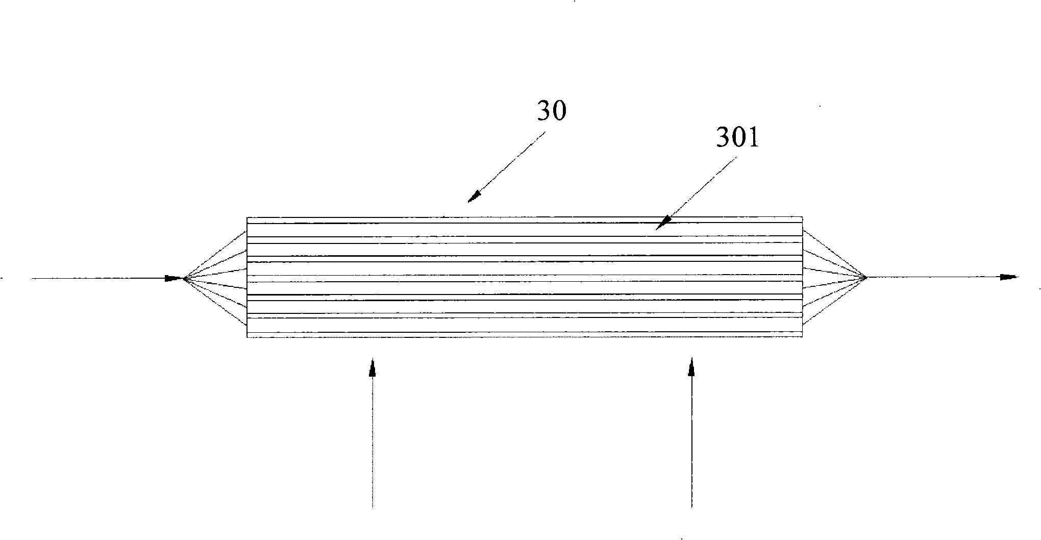
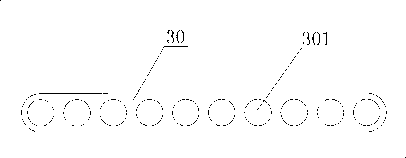
[0037] Please see Figure 4 , Figure 4 This is a cross-sectional view in the width direction of the flat tube provided by the first embodiment of the present invention.

[0038] Such as Figure 4 As shown, the flat tube 1 provided by the first embodiment of the present invention includes no less than two through holes 101 extending along the length of the flat tube. In a specific embodiment, the number of through holes 101 is ten. The number of through holes is not limited to this, and can be set arbitrarily ...


PUM


Abstract

The invention relates to the technical field of heat exchanger, in particular to a flat pipe which comprises not less than two through holes which extend along the lengthwise direction of the flat pipe. The through holes are arranged side by side along the width direction of the flat pipe. Two ends of the flat pipe along the width direction respectively form an external air influx entrance end and an external air outflux end. The section sizes of the through holes are reduced gradually along the direction from the external air influx entrance end of the flat pipe to the external air outflux end of the flat pipe. The through hole near the external air influx entrance end of the flat pipe has larger section size, larger heat transmission temperature difference, large heat exchange volume and larger mass flow. The through hole near the external air outflux end of the flat pipe has smaller section size, lower heat transmission temperature difference, less heat exchange volume and less mass flow. The invention brings the heat exchange performance of the flat pipe into play completely and improves the heat exchange efficiency of the heat exchanger further. The invention also provides a heat exchanger.

Description

Technical field [0001] The invention relates to the technical field of heat exchangers, in particular to a flat tube and a heat exchanger. Background technique [0002] In the existing refrigeration system, various forms of heat exchangers including liquid collecting tubes have roughly the same structure, and the heat exchangers of this structure can be used as evaporators or condensers. [0003] Please see figure 1 , figure 1 It is a schematic diagram of the overall structure of a typical heat exchanger in the prior art. [0004] Such as figure 1 As shown, the heat exchanger of this structure consists of a pair of parallel and separated collection tubes 10, a plurality of parallel flat tubes 30 whose two ends are respectively connected with the inner cavities of the two collection tubes 10, and are arranged in the flat tube. The fin 40 between the tubes 30 is composed of two side plates 20 fixedly connected to the two outer flat tubes 30 through the fins 40. [0005] The heat...

Claims


Application Information

Patent Timeline
Patent Type & Authority Applications(China)
IPC IPC(8): F28F1/02F28D1/053
Inventor 蒋建龙黄宁杰
Owner SANHUA(HANGZHOU) MICRO CHANNEL HEAT EXCHANGER CO LTD
Why Eureka
Try Eureka