Dew formation testing device and dew formation testing method

a testing device and dew formation technology, applied in the direction of instruments, weighing by absorbing components, material moisture content, etc., can solve the problems of difficult to maintain the dew formation on the testing sample the dew formation on the testing sample is difficult to maintain in a substantially uniform state, and the dew formation on the testing sample is difficult to achieve uniform dew formation. , to achieve the effect of uniform dew formation

Active Publication Date: 2014-07-01
MURATA MFG CO LTD +1
View PDF21 Cites 11 Cited by
  • Summary
  • Abstract
  • Description
  • Claims
  • Application Information

AI Technical Summary

Benefits of technology

[0011]It is an object of the present invention to provide a dew formation testing device and a dew formation testing method that make it possible to maintain a substantially uniform state of dew formation on a testing sample.

Problems solved by technology

However, in such testing devices, it is difficult to control accurately the flow of air inside the testing chamber and therefore the dew formation on the testing sample is difficult to maintain in a substantially uniform state.
As a result, it is difficult to maintain the dew formation on the testing sample in a substantially uniform state.
Therefore, vibrations of the air conditioning chamber are transmitted to the testing chamber.
As a result, condensation droplets are caused to merge or flow, thereby affecting the condensation state on the testing sample.
Because the testing sample is thus affected by vibrations, it is also difficult to maintain a substantially uniform state of dew formation on the testing sample.

Method used


Image

  • Dew formation testing device and dew formation testing method
  • Dew formation testing device and dew formation testing method
  • Dew formation testing device and dew formation testing method

Examples


first embodiment

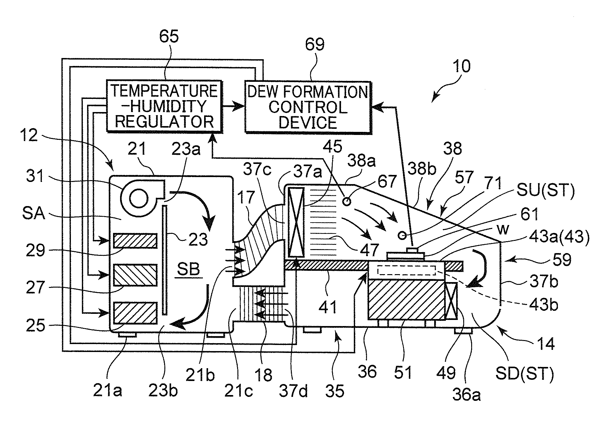
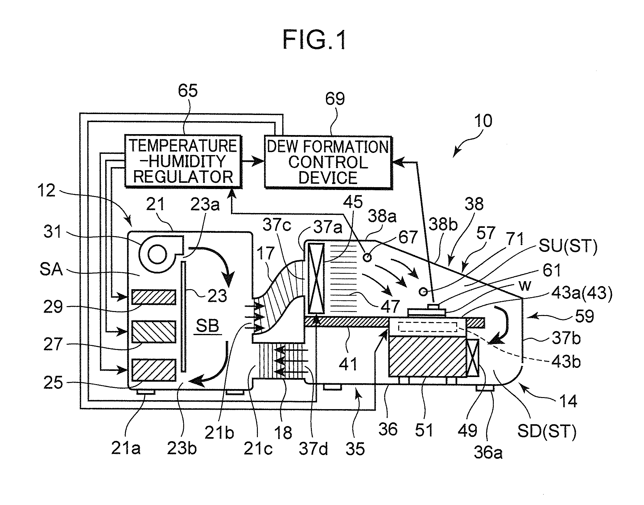
[0030]As shown in FIG. 1, a dew formation testing device 10 according to the first embodiment is provided with an adjustment tank 12 as an example of an adjusting unit, a testing tank 14, and ducts 17, 18 connecting the tanks.

[0031]The adjustment tank 12 is a section for adjusting the temperature and humidity of air supplied into the testing tank 14 to predetermined temperature and humidity. The adjustment tank 12 is provided with a hollow casing 21. Legs 21a are provided at the bottom of the casing 21, and the legs 21a are grounded.

[0032]A partition plate 23 is disposed so as to extend vertically inside the casing 21, and the adjustment tank 12 is partitioned by the partition plate 23 into an adjustment space SA and a buffer space SB. Two communication holes 23a, 23b are provided in the partition plate 23. One communication hole 23a is positioned in the upper end portion of the partition plate 23, and the other communication hole 23b is positioned in the lower end portion of the pa...

second embodiment

[0083]FIG. 12 illustrates the second embodiment of the present invention. In the second embodiment, by contrast with the first embodiment, the buffer space SB is formed inside the testing tank 14. In this case, constituent elements identical to those of the first embodiment are assigned with like reference numerals and symbols and detailed explanation thereof is herein omitted.

[0084]In the second embodiment, the partition plate 23 is not provided inside the adjustment tank 12, and the space inside the adjustment tank 12 is constituted as the adjustment space SA. The outflow port 21b and the inflow port 21c are formed in the casing 21 of the adjustment tank 12 so as to face the adjustment space SA. The upstream duct 17 is attached to the outflow port 21b, and the air blown out from the air blower 31 flows directly into the upstream duct 17. The inflow port 21c introduces the external air into the adjustment space SA.

[0085]A partition plate 75 is provided inside the testing tank 14. T...


PUM

PropertyMeasurementUnit
flow velocityaaaaaaaaaa
tilting angleaaaaaaaaaa
air flow velocityaaaaaaaaaa

Abstract

A dew formation testing device has an adjustment tank capable of adjusting the temperature and humidity of air to predetermined temperature and humidity, a testing tank installed separately from the adjustment tank and having a sample base that has a mounting surface, onto which a testing sample W can be placed, and that is capable to cool the mounting surface, and ducts that link the adjustment unit and the testing tank. The testing tank is provided with an air guide member that, when air flowing into the testing tank through the duct flows onto the sample base from a side of the sample base, guides the air in the direction tilted downward at a predetermined angle, the guidance being performed at a position right above the sample base at an end thereof which is on the upstream side of the air flow.

Description

BACKGROUND OF THE INVENTION[0001]1. Field of the Invention[0002]The present invention relates to a dew formation testing device and a dew formation testing method.[0003]2. Description of the Related Art[0004]Dew formation testing devices that can perform dew formation testing have been known, as described in JP 2007-271551, JP 3113823 and JP 5-164684.[0005]The dew formation testing device disclosed in JP 2007-271551 has a full-body tank constituted by thermally insulating panels. A testing chamber, a low-temperature adjustment tank, and a high-temperature adjustment tank are included in the full-body tank. The low-temperature adjustment tank is provided below the testing chamber, and low-temperature and low-humidity air is generated in the low-temperature adjustment tank. An introducing port damper and a discharge port damper for performing / stopping the circulation of the air between the testing chamber and the low-temperature adjustment tank are provided in the floor panel of the t...

Claims


Application Information

Patent Timeline
Patent Type & Authority Patents(United States)
IPC IPC(8): G01N25/68G01N17/00
CPCG01N17/00G01N25/68
Inventor SHIMADA, TETSUYATANAKA, HIROKAZUOKAMOTO, AKIRAMIZUMA, YOSHINORIOKADA, SEIICHI
Owner MURATA MFG CO LTD
Why Eureka
Try Eureka