Method for operating a gas turbo group

a gas turbine and group technology, applied in the direction of combustion types, turbine/propulsion engine ignition, combustion using catalytic materials, etc., can solve the problems of gas turbo groups, unit performance cannot be achieved with catalytic combustion chambers, and the limit of achievable temperatures

Inactive Publication Date: 2004-11-04
ALSTOM TECH LTD
View PDF7 Cites 24 Cited by
  • Summary
  • Abstract
  • Description
  • Claims
  • Application Information

AI Technical Summary

Benefits of technology

[0011] According to another embodiment of the invention, the combustion air mass flow is increased by cooling the suction air upstream from the compressor, and conversely is reduced by reducing the cooling power applied for cooling.
[0018] During a load rejection, a preferred and advantageous embodiment of the method according to the invention provides that at first the second, non-catalytic burner stage is directly shut off, so that the compressor outlet temperature falls to idle level. The compressor pre-guide row remains standing open for several seconds. At the same time, or immediately after the second burner stage is shut off, the fuel mass flow supplied to the preburner is greatly increased, and the preburner stage is preferably operated with a predetermined, high fuel mass flow, in order to prevent the extinction of the catalyst of the catalytic burner stage; after this, the fuel quantity of the preburner stage can be adjusted to the fuel quantity necessary in idle operation of the gas turbo group. The fuel quantity supplied to the catalytic burner stage is hereby regulated in such a way that the rotor speed of the gas turbine is restricted to the nominal speed. During a subsequent load increase, the second burner stage is then again taken into operation again in order to regulate the load.

Problems solved by technology

However, a disadvantage in using gas turbo groups is the limitation of achievable temperatures, which is necessary in particular because of life span considerations.
The turbine inlet temperatures that are desirable today in the interest of good efficiencies and high unit performance cannot be achieved with catalytic combustion chambers alone: While the combustion chambers of modern gas turbines generate hot gas temperatures of, for example, about 1450.degree. C., a catalytic combustion chamber can only be operated up to temperatures of approximately 1000.degree. C.
The preparation of the fuel-air mixture for the catalytic burner stage used in this publication is, however, very complicated and expensive.
In addition, under a full load, the preparation stage should be shut down, which means that it is not possible to react adequately to rapid load changes.
Intermittent operation of the catalytic stage also causes undesired and even damaging thermal shocks to the frequently ceramic carrier material of the catalyzer.

Method used


Image

  • Method for operating a gas turbo group
  • Method for operating a gas turbo group
  • Method for operating a gas turbo group

Examples


Embodiment Construction

[0007] It is the objective of the invention to disclose a method of the aforementioned type that avoids the disadvantages of the state of the art. In particular, the objective is to specify an operating concept for a gas turbo group with a combustion chamber having a catalytic stage in such a way that the favorable emission behavior of the catalytic stage will be effective over the largest possible power range.

[0008] This objective is realized with the method according to Claim 1. Advantageous designs of the method are the subject matter of the secondary claims or can be found in the following specification and exemplary embodiments.

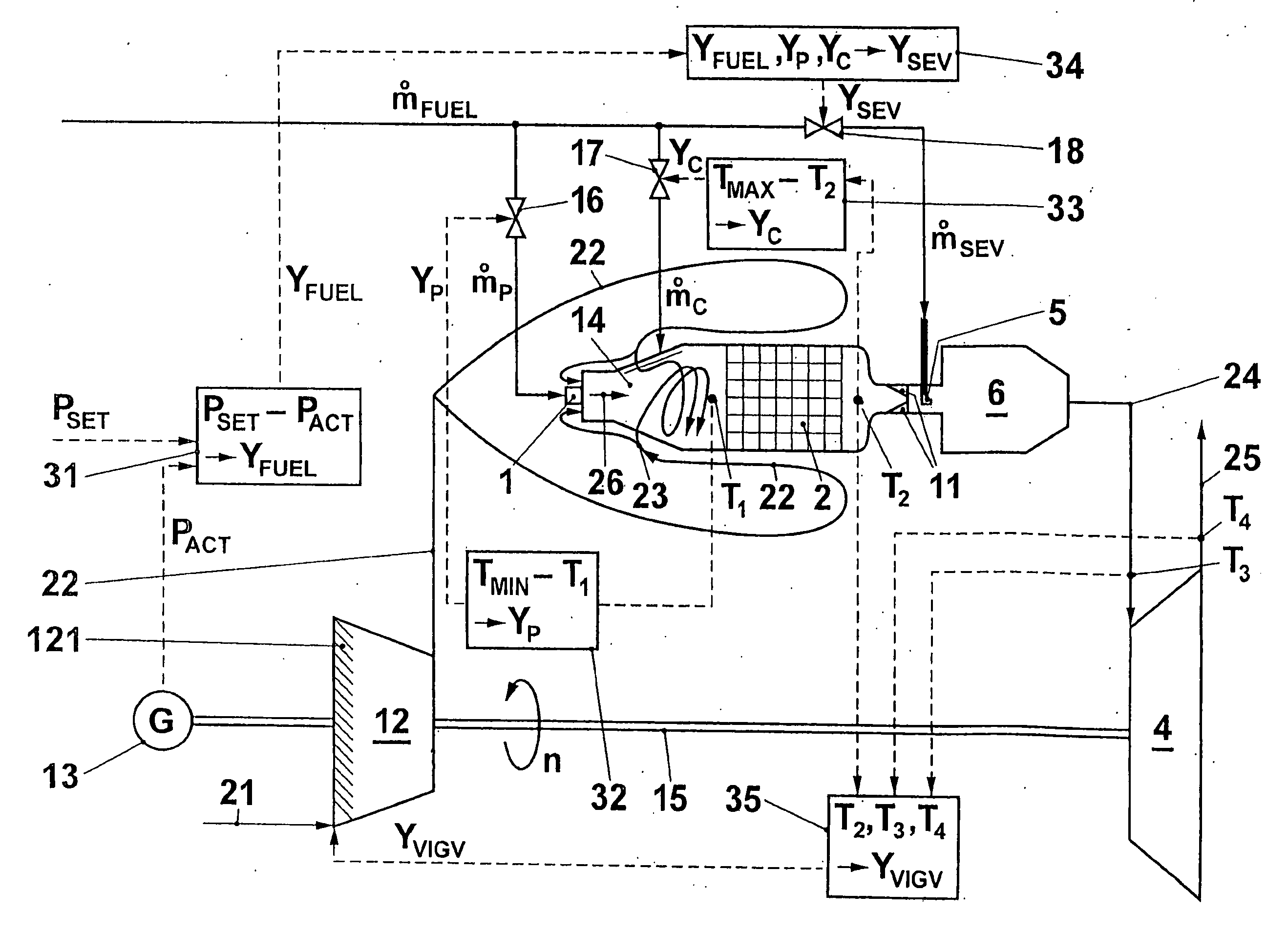
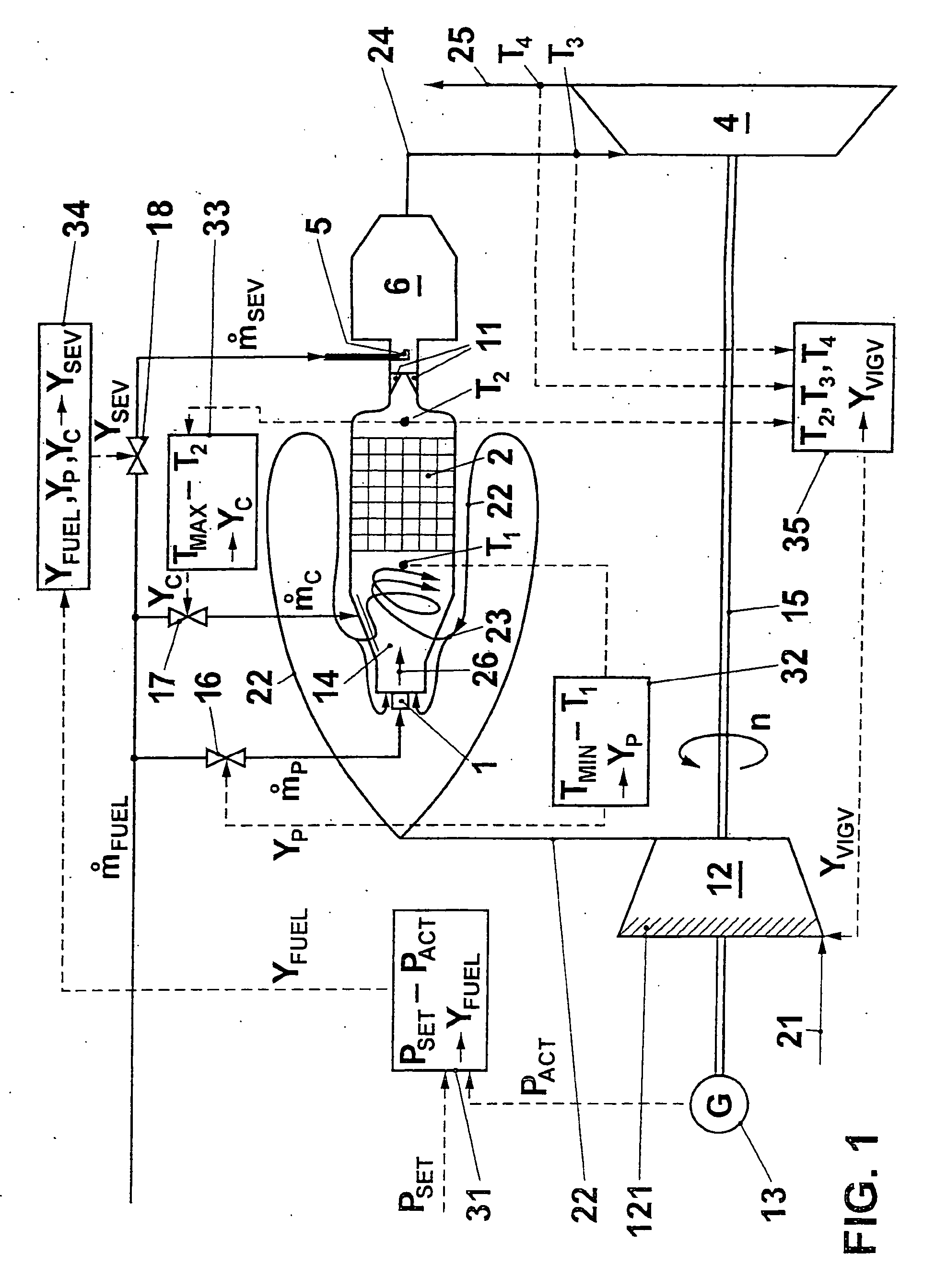
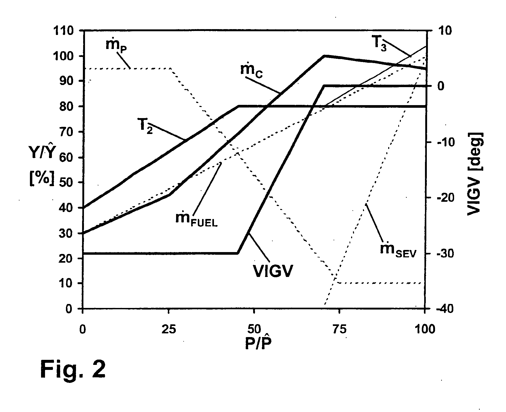
[0009] The core of the invention therefore consists of varying the combustion air mass flow in a gas turbo group having a catalytic stage and a following, non-catalytic stage in such a way that, with a variable fuel mass flow, the temperature at the outlet of the catalytic stage remains as constant as possible, and only then feeding additional fuel to th...


PUM


Abstract

A gas turbo group has a combustion chamber comprising a catalytic burner stage (2), a preburner stage (1) located upstream from the catalytic burner stage, as well as a non-catalytic burner stage (11, 5, 6) located downstream from the catalytic burner stage. The preburner stage serves to always maintain a temperature (T1) at the inlet into the catalytic stage that corresponds at least to a minimum temperature (TMIN) necessary for operating the catalytic burner stage. According to the invention, the gas turbo group is operated so that the burner stage located downstream from the catalytic combustion chamber is taken into operation only when the temperature (T2) at the outlet from the catalytic stage has reached an upper limit in the presence of a maximum combustion air mass flow.

Description

[0001] This application claims priority under 35 U.S.C. .sctn. 119 to Swiss patent application number 2003 0199 / 03, filed 11 Feb. 2003, by Jaan Hellat et al., the entirety of which is incorporated by reference herein.TECHNICAL FIELD OF APPLICATION[0002] The present invention relates to a method for operating a gas turbo group.STATE OF THE ART[0003] The catalytic conversion of fuels presents an opportunity for generating heat with few noxious substances. However, a disadvantage in using gas turbo groups is the limitation of achievable temperatures, which is necessary in particular because of life span considerations. The turbine inlet temperatures that are desirable today in the interest of good efficiencies and high unit performance cannot be achieved with catalytic combustion chambers alone: While the combustion chambers of modern gas turbines generate hot gas temperatures of, for example, about 1450.degree. C., a catalytic combustion chamber can only be operated up to temperatures...

Claims


Application Information

Patent Timeline
Patent Type & Authority Applications(United States)
IPC IPC(8): F02C7/26F02C9/28F23R3/40
CPCF02C7/26F02C9/28F05D2270/083F23C13/02F23C13/06F23C2900/13002F23N2041/20F23R3/40F05D2270/304F23N2241/20
Inventor HELLAT, JAANTSCHIRREN, STEFANDITTMANN, ROLF
Owner ALSTOM TECH LTD
Why Eureka
Try Eureka