Liquid cooled fuel injection valve and method of operating a liquid cooled fuel injection valve

a fuel injection valve and liquid cooled technology, which is applied in the direction of fuel injecting pumps, machines/engines, mechanical equipment, etc., can solve the problems of heat deformation of the injector tip body, the cooling provided by the flow of liquid diesel fuel through the fuel injection valve may not be sufficient to cool the injector tip, and the need for auto-ignition of much higher temperatures and pressures. achieve the effect of being durable and affordabl

Inactive Publication Date: 2005-10-13
WESTPORT POWER
View PDF12 Cites 23 Cited by
  • Summary
  • Abstract
  • Description
  • Claims
  • Application Information

AI Technical Summary

Benefits of technology

[0020] The drain valve is preferably spring biased so that it does not open unless fuel pressure within the fuel cavity is greater than a predetermined set point. By controlling fuel pressure within a range of pressures, the drain valve is operable independently from actuation of the valve member. For example, when the fuel pressure within the fuel cavity is less than the predetermined set point, the drain valve remains closed while fuel is injected into the combustion chamber during an injection event. As long as the pressure within the fuel cavity is higher than the predetermined set point, the drain valve can be open, even during a fuel injection event. The ability to control when cooling occurs, for example by controlling fuel pressure, allows cooling to be controlled independently of valve member movement and timing for fuel injection events, providing an advantage over prior art arrangements.
[0021] A “simple” spring biased drain valve does not comprise a controller or actuator. An advantage of a simple spring biased drain valve assembly is that it automatically closes when pressure is less than a predetermined set point, it is compact so that it can be disposed within the fuel injection valve, and it is inexpensive and durable.

Problems solved by technology

A problem with gaseous fuels such as natural gas is that, compared to diesel fuel, much higher temperatures and pressures are needed for auto-ignition.
However, the quantity of pilot diesel fuel that is injected into the combustion chamber to trigger ignition of the gaseous fuel is much less than the quantity of diesel fuel that would be injected into the combustion chamber in a conventional diesel-fueled engine.
When the diesel fuel consumption is this low, the cooling provided by the flow of liquid diesel fuel through the fuel injection valve may not be sufficient to cool the injector tip when peak combustion chamber temperatures are reached.
If the injector tip overheats, possible consequences include, heat deformation of the injector tip body and fuel “coking”, a condition created by fuel being exposed to reducing conditions.
Accordingly, a problem with this arrangement is that it can result in significant parasitic loads during start-up and idling conditions.
Also, because the timing for draining fuel is indiscriminant, in that an amount of fuel is drained with every injection event, this arrangement may require a larger fuel pump than would otherwise be required.
With this arrangement, fuel is drained in each cycle regardless of whether the engine is starting up or already running, again resulting in significant parasitic loads at times when it is desirable to reduce parasitic loading.
A problem with this arrangement is the complexity of the drain valve and throttle arrangement, which adds a high pressure drain system downstream from the fuel injection valve, with joints connecting the high pressure drain line to the fuel injection valve body, the drain valve, and the throttle.
As noted with respect to the references already presented, continuously draining pilot fuel from the fuel supply system or the nozzle cavity increases the parasitic load on the fuel supply system and could require a larger fuel supply pump.

Method used


Image

  • Liquid cooled fuel injection valve and method of operating a liquid cooled fuel injection valve
  • Liquid cooled fuel injection valve and method of operating a liquid cooled fuel injection valve
  • Liquid cooled fuel injection valve and method of operating a liquid cooled fuel injection valve

Examples


Embodiment Construction

)

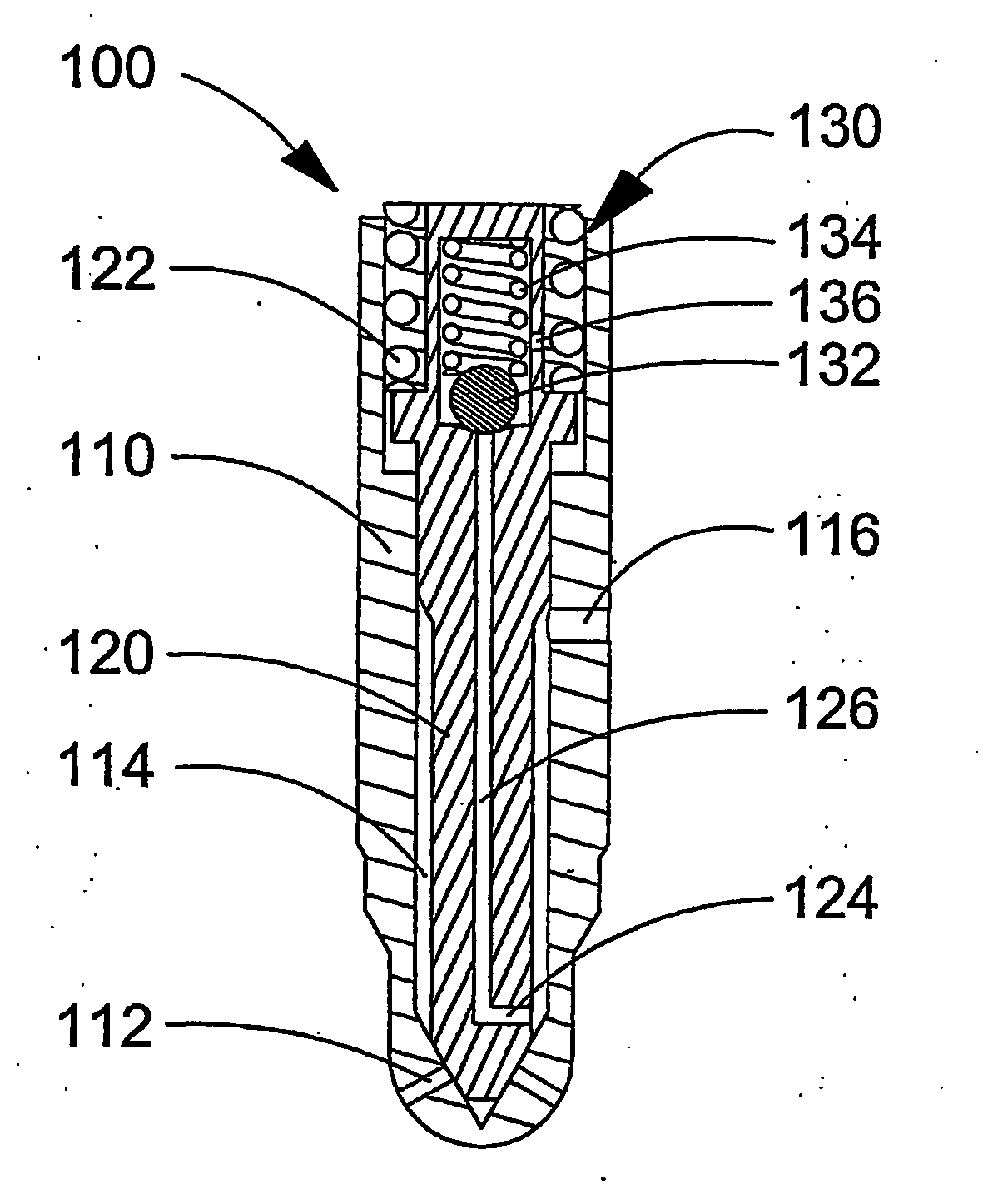
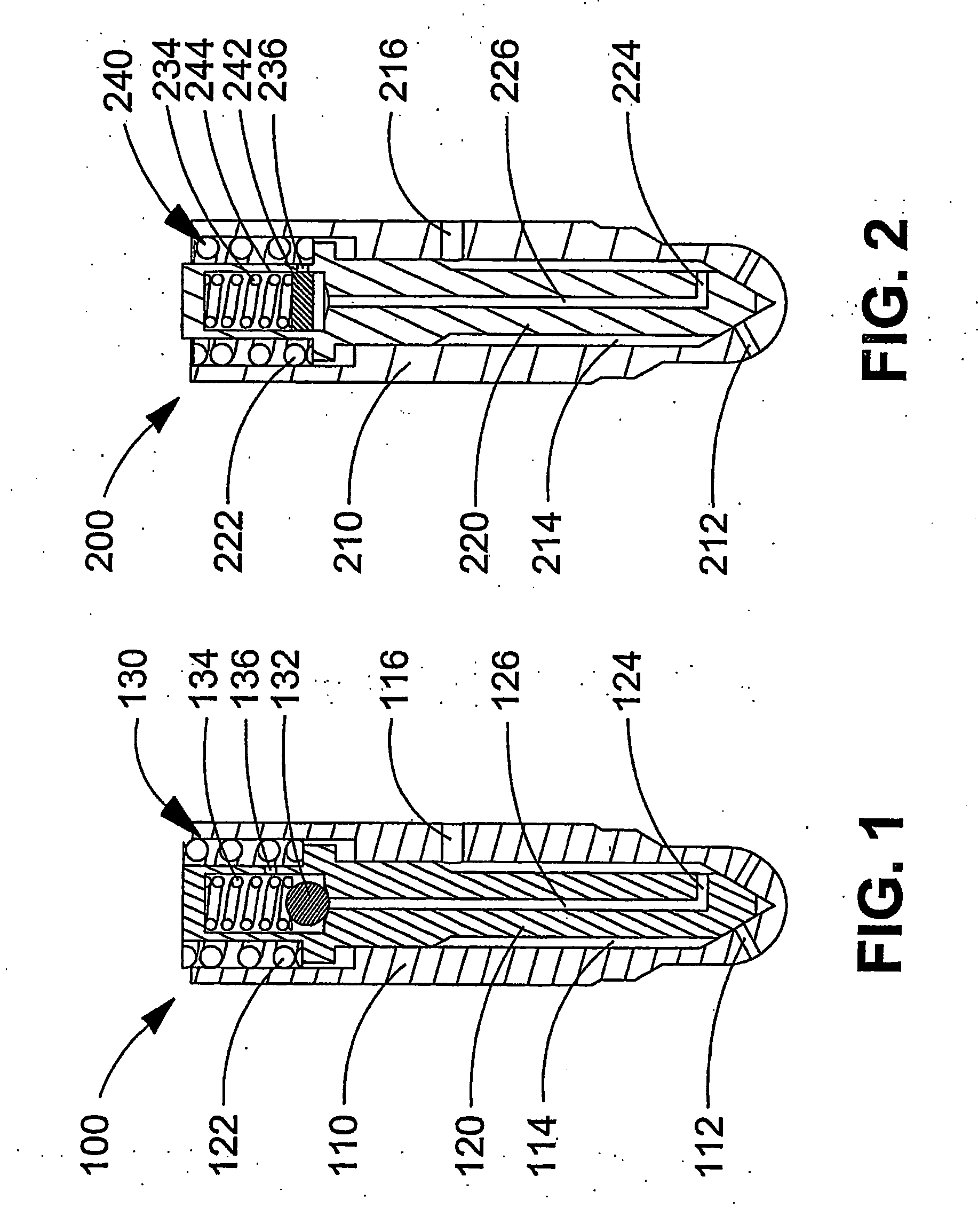
[0066] A liquid cooled fuel injection valve is capable of using a portion of the liquid fuel contained within a fuel cavity provided within an injector tip to act as a liquid coolant for cooling the injector tip. A spring biased drain valve located within the body of the fuel injection valve or within the injection valve needle prevents fuel from flowing to drain when cooling is not required. The timing for cooling can be controlled by controlling fuel pressure within the fuel cavity whereby the drain valve is closed when fuel pressure is less than a predetermined set point. That is, the drain valve opens when fuel pressure within the fuel cavity is greater than the predetermined set point.

[0067] At start up, fuel pressure within the fuel cavity is initially low, so the drain valve can be calibrated to open after start up is over. In a preferred method, pressure within the fuel cavity is controlled so that the drain valve is shut during start up, when the engine is idling, during ...


PUM


Abstract

A liquid cooled fuel injection valve is operable to inject fuel directly into a combustion chamber through a nozzle orifice provided in an injector tip. The fuel injection valve further comprises a cooling system for draining fuel from a fuel cavity disposed within the injector tip and a drain valve that opens when pressure within the fuel cavity is greater than a predetermined set point. Fuel drained through the cooling system is directed to a drain system that may be combined with drain passages typically found in fuel injection valves. In a preferred embodiment, the drain valve is disposed within the fuel injection valve.

Description

CROSS-REFERENCE TO RELATED APPLICATION(S) [0001] This application is a continuation of International Application No. PCT / CA2003 / 001493, having an international filing date of Sep. 26, 2003, entitled, “Liquid Cooled Fuel Injection Valve And Method Of Operating A Liquid Cooled Fuel Injection Valve”. International Application No. PCT / CA2003 / 001493 claimed priority benefits, in turn, from Canadian Patent Application No. 2,405,350 filed Sep. 26, 2002. International Application No. PCT / CA2003 / 001493 is also hereby incorporated by reference herein in its entirety.FIELD OF THE INVENTION [0002] The present invention relates to a liquid cooled fuel injection valve and a method of operating a liquid cooled fuel injection valve. More particularly, the invention relates to an apparatus and method for using fuel as the cooling medium and controlling when cooling occurs. BACKGROUND OF THE INVENTION [0003] A fuel injection valve comprises a nozzle, also known as an injector tip, which is inserted i...

Claims


Application Information

Patent Timeline
Patent Type & Authority Applications(United States)
IPC IPC(8): F02M53/04F02M55/00F02M61/10F02M61/16
CPCF02D19/0605F02D19/10F02M53/043F02M55/002F02M61/10F02M61/16Y02T10/32F02D19/0689F02D19/0694F02M21/0263F02M21/0287Y02T10/36Y02T10/30
Inventor BAKER, S. MICHAELPERR, VICTOR J.FREE, P. DOUGLAS
Owner WESTPORT POWER
Why Eureka
Try Eureka