Method and Structure for Tiling Industrial Thin-Film Solar Devices

a solar device and transparent cover technology, applied in the field of photovoltaic techniques, can solve the problems of reducing reducing the efficiency reducing the cost of solar energy generation, so as to improve the power capacity of solar modules and reduce the cost of packaging process and material. the effect of cost saving

Active Publication Date: 2011-08-25
CM MFG
View PDF93 Cites 40 Cited by
  • Summary
  • Abstract
  • Description
  • Claims
  • Application Information

AI Technical Summary

Benefits of technology

[0009]It is to be appreciated that the present invention provides numerous benefits over conventional techniques. Among other things, the method and structure provided in the present invention are compatible but scaled to very large industrial panels from conventional modules, which allow cost effective implementation of new generation integrated thin-film photovoltaic modules into large scale commercial applications. The integrated solar module laminates two or more thin-film photovoltaic devices to a common cover plate. This effective enhances the power capacity of the solar module by extending either circuit current delivered from the entire module or the voltage level for coupling with outside electric contacts. Physically, each of the two or more thin-film solar devices can have a dimension of 65 cm times 165 cm and be disposed side by side onto a hardened glass plate having a dimension of 165 cm or greater in one direction. The encapsulation of the integrated module is compatible with stand alone module, so that additional cost saving in packaging process and material can be achieved by implementation of current invention. Additionally, scale up the stand alone thin-film solar device and their integration provide high quality with reduced cost but enhanced overall efficiency over 11%. There are other benefits as well.

Problems solved by technology

Unfortunately, the supply of petrochemical fuel is limited and essentially fixed based upon the amount available on the planet Earth.
Additionally, as more people use petroleum products in growing amounts, it is rapidly becoming a scarce resource, which will eventually become depleted over time.
Although solar energy is environmentally clean and has been successful to a point, many limitations remain to be resolved before it becomes widely used throughout the world.
However, crystalline materials are often costly and difficult to make on a large scale.
Similar limitations exist with the use of thin film technology in making solar cells.
That is, efficiencies are often poor.
Additionally, film reliability is often poor and cannot be used for extensive periods of time in conventional environmental applications.
Often, thin films are difficult to mechanically integrate with each other.

Method used


Image

  • Method and Structure for Tiling Industrial Thin-Film Solar Devices
  • Method and Structure for Tiling Industrial Thin-Film Solar Devices
  • Method and Structure for Tiling Industrial Thin-Film Solar Devices

Examples


Embodiment Construction

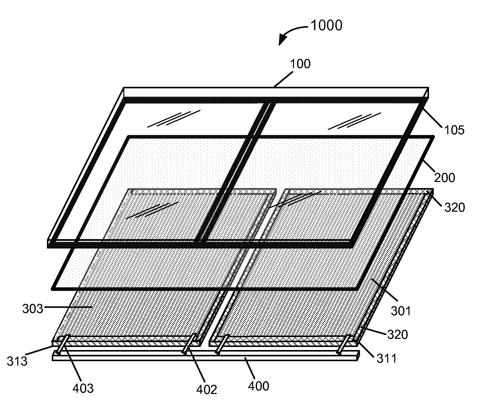
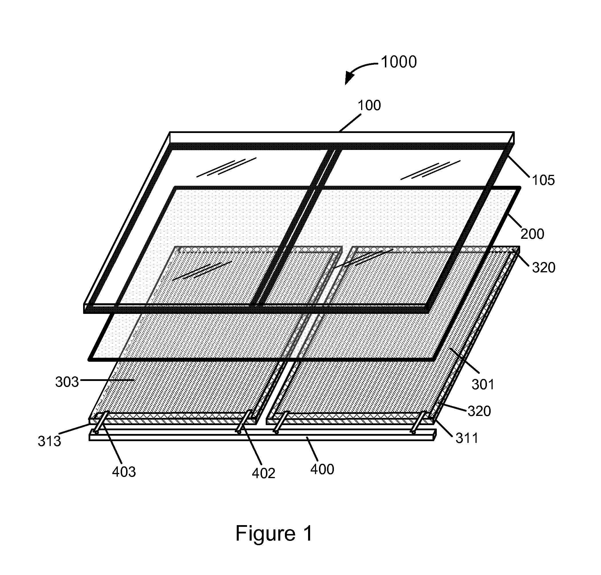
[0016]FIG. 1 is a perspective view of a method and structure for tiling solar devices according to an embodiment of the present invention. This diagram is merely an example, which should not limit the scope of the claims herein. As shown, a structure 1000 for tiling solar devices on to a cover plate is schematically broken down to a group of basic elements. In an embodiment, the structure 1000 includes a cover plate 100, two or more solar devices 301 and 303 respectively formed on a substrate 311 and 313, a sealant material 320, a fill material 200, a common conductor 400, and a plurality of ribbon conductor 402. The cover plate is typically flat with a front surface on light-receiving side and a rear surface for attaching one or more solar devices. The cover plate 100 has a thickness in the range of 0.5-10 mm, preferably 1-5 mm, and can be of any material that has sufficient transparency above the photovoltaic layer. Suitably the cover plate is a cover glass, preferably hardened gl...


PUM


Abstract

A method for integrating photovoltaic module includes providing a cover plate having a first surface and a second surface opposed to the first surface and supplying photovoltaic devices respectively formed on substrates. The photovoltaic devices include photovoltaic cells electrically coupled to each other, and each cell is characterized by a thin-film photovoltaic layer sandwiched between a first electrode material and a second electrode material. The first electrode material overlies the substrate and the second electrode material overlies the thin-film photovoltaic layer. The method further includes disposing the solar devices side by side to laminate with the cover plate by means of a first organic material filled between the second electrode material and the second surface. Each of the solar devices has a peripheral edge region being sealed by a second organic material. The method further includes electrically coupling the solar devices to each other.

Description

CROSS-REFERENCE TO RELATED APPLICATION[0001]This application claims priority to U.S. Provisional Patent Application No. 61 / 297,661, filed Jan. 22, 2010, entitled “Method and Structure for Tiling Industrial Thin-Film Solar Devices” by inventor Robert D. Wieting, commonly assigned and incorporated by reference herein for all purposesBACKGROUND OF THE INVENTION[0002]The present invention relates generally to photovoltaic techniques. More particularly, the present invention provides a method and structure for tiling solar devices to a transparent cover plate. Merely by example, embodiments of the present invention are applied to laminate two or more industrial-sized solar panels based on thin-film photovoltaic materials including copper indium diselenide species (CIS), copper indium gallium diselenide species (CIGS), and / or others.[0003]From the beginning of time, mankind has been challenged to find way of harnessing energy. Energy comes in the forms such as petrochemical, hydroelectric...

Claims


Application Information

Patent Timeline
Patent Type & Authority Applications(United States)
IPC IPC(8): H01L31/042H01L31/18
CPCH01L31/0201H01L31/02013H01L31/048Y02E10/541H01L31/0749Y02E10/50H01L31/0504
Inventor WIETING, ROBERT D.
Owner CM MFG
Why Eureka
Try Eureka