Pipette

a pipette and pipette technology, applied in the field of pipette, can solve the problems of inaccurate or expensive manufacture of devices, and achieve the effect of inaccuracy readings

Active Publication Date: 2017-05-23
ACCESS BIO
View PDF15 Cites 3 Cited by
  • Summary
  • Abstract
  • Description
  • Claims
  • Application Information

AI Technical Summary

Benefits of technology

[0008]The present invention also provides for a pipette that can dispense precise amounts of fluid from the pipette using bulbs. While the sample can be collected into the capillary tube, the drawing technique provided by the present invention prevents unwanted air into the capillary tube, thereby preventing air bubbles being ejected with the sample and providing inaccurate readings. For example, the lower bulb in a double-bulb pipette, or the lower portion of the bulb in a single bulb pipette, can aid in the removal of air bubbles from the capillary tube.

Problems solved by technology

These devices are, for the most part, inaccurate or expensive to manufacture.

Method used


Image

  • Pipette
  • Pipette
  • Pipette

Examples


embodiment 1

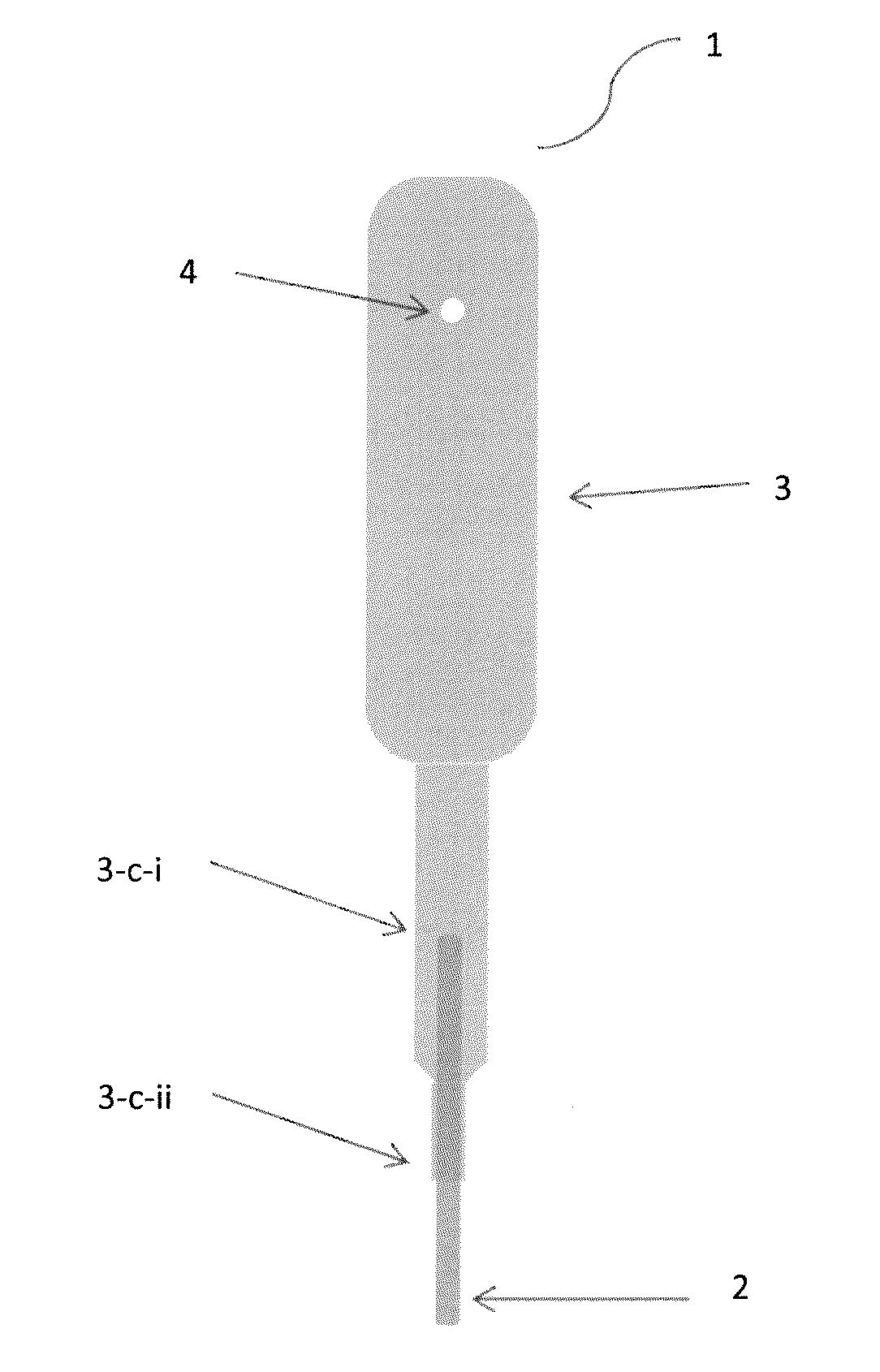
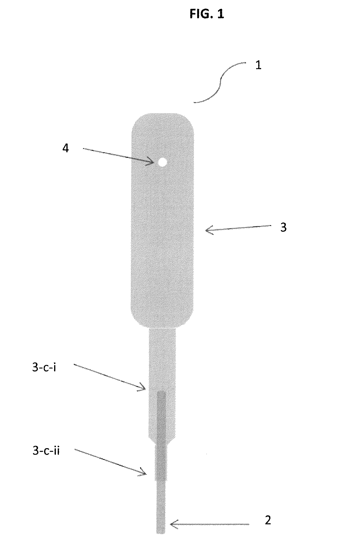
[0053]In embodiment 1, there is provided a pipette for delivering a precisely measured volume of liquid having:

[0054]a capillary tube (2) configured to draw liquid by capillary action, the capillary tube having a lower open end and an upper open end; and

[0055]a chamber (3) being structurally connected to the upper end of the capillary tube; the chamber having an orifice (4) in the upper portion of the chamber;

[0056]wherein,

[0057]the chamber extends to a middle tube extension (3-c-i) and continues to a bottom tube extension (3-c-ii); the bottom tube extension being integrally united to the capillary tube at the lower end of the bottom extension;

[0058]the orifice is on one sidewall of the chamber at a selected distance from the open end; and

[0059]the capillary tube has a diameter and a height of a predetermined measurement such that a precise collection of from about 0.1 μL to about 200 μL of a liquid is drawn by capillary action.

embodiment 2

[0060]In embodiment 2, there is provided a pipette for delivering a precisely measured volume of liquid having:

[0061]a capillary tube (2) configured to draw liquid by capillary action, the capillary tube having a lower open end and an upper open end; and

[0062]a chamber (3) being structurally connected to the upper end of the capillary tube; the chamber having an orifice (4) in the upper portion of the chamber;

[0063]wherein,

[0064]the chamber extends to a bottom tube extension (3-c-ii); the bottom tube extension being integrally united to the capillary tube at the lower end of the bottom extension;

[0065]the orifice is on one sidewall of the chamber at a selected distance from the open end; and

[0066]the capillary tube has a diameter and a height of a predetermined measurement such that a precise collection of from about 0.1 μL to about 200 μL of a liquid is drawn by capillary action.

[0067]In embodiment 3, there is provided a pipette according to embodiment 1 or 2, wherein the chamber i...

embodiment 4

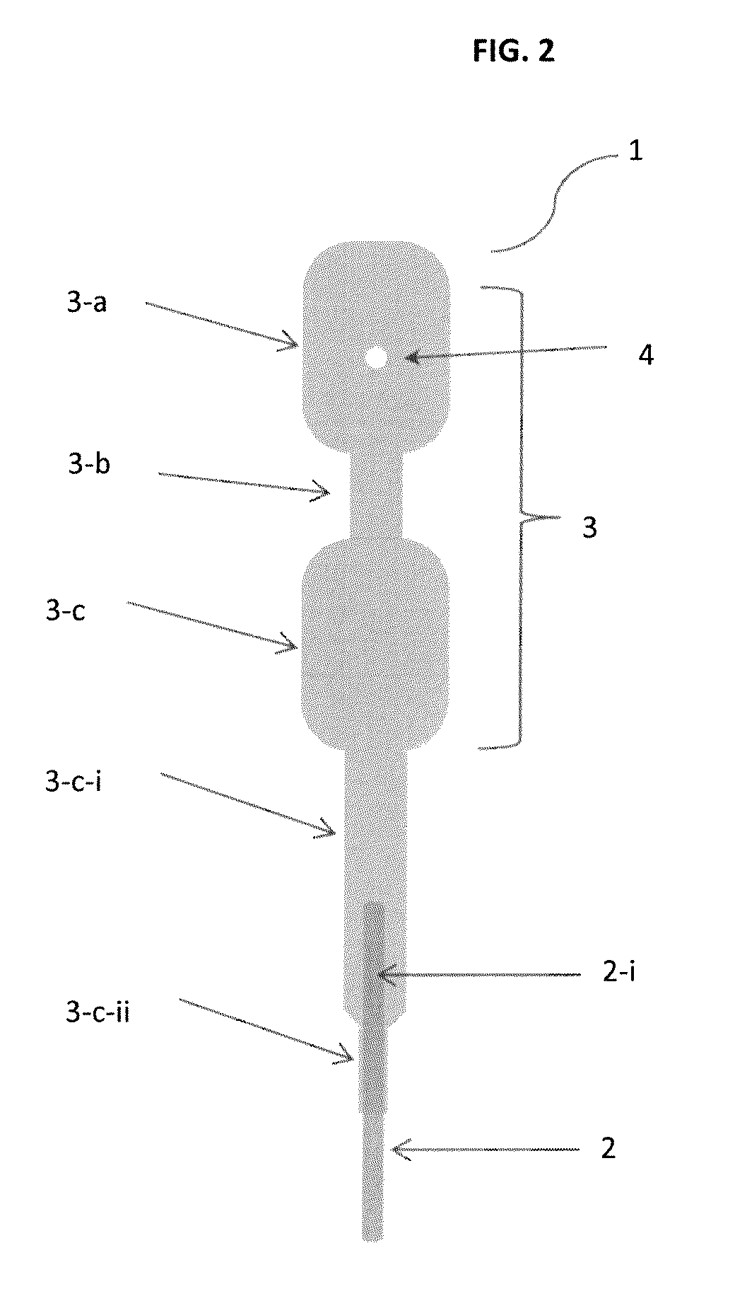
[0068]In embodiment 4, there is provided a pipette for delivering a measured volume of liquid having:

[0069]a capillary tube (2) configured to draw liquid by capillary action, the capillary tube having a lower open end and an upper open end; and

[0070]a chamber (3) being structurally connected to the upper end of the capillary tube, the chamber comprising an upper bulb and a lower bulb connected by a connection tube, wherein the upper bulb comprises an orifice;

[0071]wherein,

[0072]the chamber extends to a middle tube extension and continues to a bottom tube extension, the bottom tube extension being integrally united to the capillary tube at the lower end of the bottom extension;

[0073]the orifice is made through one sidewall of the upper bulb of the chamber; and

[0074]the capillary tube has a diameter and a height of a predetermined measurement such that a precise collection of from about 0.1 μL to about 200 μL of a liquid is drawn by capillary action.


PUM


Abstract

A pipette for delivering a measured volume of liquid having an elongated hollow tubular body (or capillary tube) (2) configured to draw liquid by capillary action, the hollow tubular body having a lower open end and an upper open end; and a chamber (3) structurally connected to the upper end of the tubular body (2), the chamber having an orifice (4) in the upper portion of the chamber.

Description

CROSS-REFERENCE TO RELATED APPLICATION[0001]This application claims the benefit of priority from U.S. Provisional Patent Application No. 61 / 746,970 filed Dec. 28, 2012, the contents of which are incorporated herein by reference.FIELD OF THE INVENTION[0002]The invention relates to a pipette for collecting and subsequent dispensing of a precise quantity of fluid.BACKGROUND OF THE INVENTION[0003]Pipettes and capillary tubes have long been used to collect and dispense fluids. Various types of devices are known for dispensing a volumetric quantity of liquid, such as standard glass and plastic pipettes, serological pipettes, calibrated capillary tubes, conventional medicine or eye droppers, air and positive displacement pipettes and syringes. These devices are, for the most part, inaccurate or expensive to manufacture.[0004]Pipettes generally involve a tube of glass having a narrowed or restricted tip at one end and a soft or flexible bulb assembled onto the opposite end. While the volume...

Claims


Application Information

Patent Timeline
Patent Type & Authority Patents(United States)
IPC IPC(8): B01L3/02
CPCB01L3/021B01L2200/0605B01L2300/0838B01L2400/0406B01L2400/0481
Inventor KWAK, JOON HYEOKKOO, TAE-HEEKIM, HYEONSUKCHOI, YOUNG HO
Owner ACCESS BIO
Why Eureka
Try Eureka