Sensor arrangement and use of sensor arrangement

a technology of sensor arrangement and arrangement, which is applied in the direction of external support, instruments, packaging, etc., can solve the problems of shortening the life of the sensor, affecting the sensitivity of temperature measurement, and affecting the sensitivity of the temperature measurement, so as to achieve sufficient stability and improve the sensitivity of temperature measuremen

Active Publication Date: 2017-02-02
TETRA LAVAL HLDG & FINANCE SA
View PDF0 Cites 0 Cited by
  • Summary
  • Abstract
  • Description
  • Claims
  • Application Information

AI Technical Summary

Benefits of technology

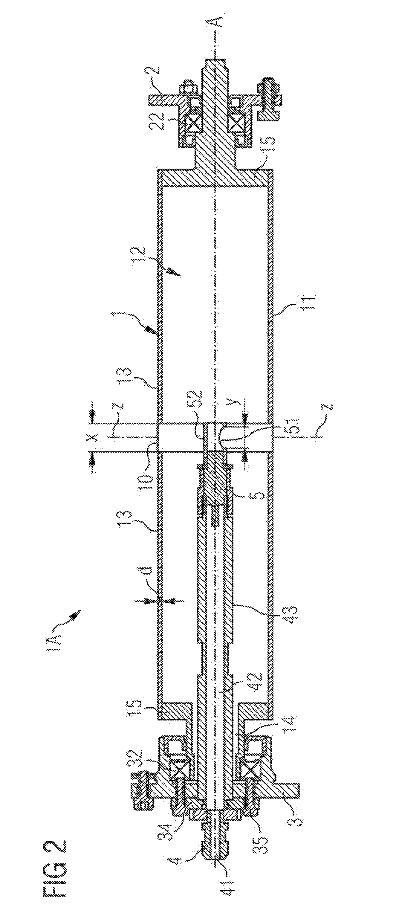
[0021]In a further embodiment, the sensor comprises a shielding that prevents undesired radiation from reaching the sensor and resulting in wrong readings. The shielding may surround at least partly the sensor or more particularly the temperature sensitive sensor head and act also as a radiation guide having one or more reflecting or mirroring areas, reflecting radiation (corresponding to temperature) towards the sensor.
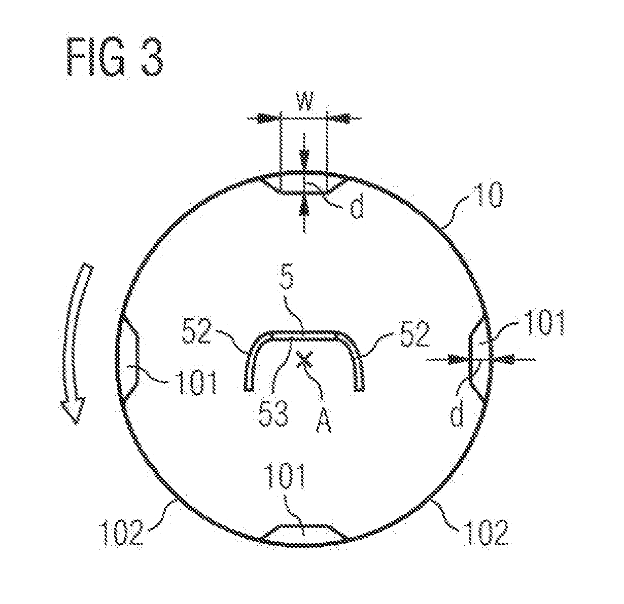
[0022]In an embodiment, the temperature sensitive head of the sensor is arranged substantially parallel to the horizontal axis and the shielding is placed in front of the sensor head with some space in between. In such embodiment, the shielding prevents radiation from direction substantially parallel to the horizontal axis. Radiation with a portion perpendicular to the horizontal axis may be received by the sensor, said radiation coming from the first and second portion, respectively.
[0023]The shielding may contain an opening facing the second portion of the sheathing. Reflective areas on an inner surface of the shielding are provided to reflect radiation entering through the opening towards the temperature sensitive head of the sensor. Thereby, particularly radiation from the second portion reaches the sensor head, while radiation from other directions is reflected by the shielding, further improving the sensitivity of temperature measurement.
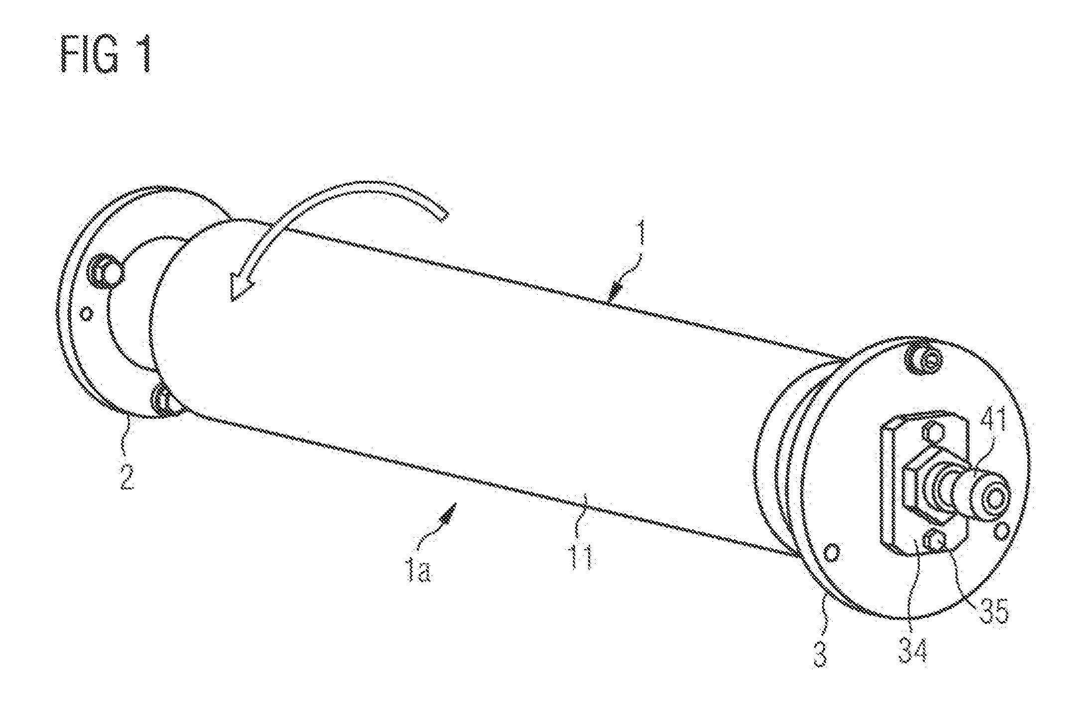
[0024]In an embodiment, the sensor may be placed on a proximal end of a non-rotating shaft arranged centrically along the horizontal axis of the sheathing and the roller. The shaft comprises and opening at the distal end providing feed-through holes for current and signal connections to the sensor. The shaft is not in contact with the sheathing, but rigidly attached to a detachable flange. The sheathing, however, is pivot-mounted on said flange. In an embodiment the sheathing is pivot mounted between two flanges to provide sufficient stability at high rotation frequencies.

Problems solved by technology

However, this is not always suitable, if the material is transported at high speeds, thereby causing mechanical stress on the sensor and the material itself.
Small variations or fluctuation of the material positions at such high speeds may damage the sensor or leading to a shorter lifetime.
In other applications chemical agents are used and a sensor in contact with such agent may produce distorted signals.

Method used


Image

  • Sensor arrangement and use of sensor arrangement
  • Sensor arrangement and use of sensor arrangement
  • Sensor arrangement and use of sensor arrangement

Examples


Embodiment Construction

[0035]FIG. 4 illustrates schematically a filling machine for filling consumable liquids into carton based packages. The term carton based packages include packages of any shape size of form having at least one fiber, pulp, paper or carton layer arranged between laminate layers. The packaging material can be supplied in form of a web or in blanks.

[0036]The filling machine comprises a packaging material magazine 6 for supplying packaging material 6A to a filling station 8 within the filling machine. Filling station 8 is arranged after a sterilization unit 7 to sterilize the packaging material before being filled with liquid.

[0037]The exemplary sterilization unit contains a bath of hydrogen-peroxide solution or a hydrogen-peroxide gas filled space. The packaging material to be sterilized is transported / moved through the bath or the gas filled space inside unit 7, respectively. The hydrogen-peroxide kills all germs and bacteria on the material, thereby sterilizing the packaging material...


PUM

PropertyMeasurementUnit
thicknessaaaaaaaaaa
thicknessaaaaaaaaaa
thicknessaaaaaaaaaa

Abstract

A sensor arrangement for temperature measurement of a material comprises a roller device with a sheathing configured such that the material can be rolled upon the sheathing. The sheathing comprises a first circumferential portion and a second portion, wherein a thickness of the sheathing in the first circumferential portion is greater than a thickness of the sheathing in the second portion. A temperature sensor arranged in a cavity inside the sheathing in proximity of the second portion.

Description

[0001]The present invention relates to a sensor arrangement for temperature measurement of a material and to a use of such sensor arrangementBACKGROUND OF THE INVENTION[0002]Some applications request a temperature measurement for a material whose temperature shall be measured, as further or correct processing require certain temperature. For this purpose, a temperature sensor measuring the temperature of material can be in direct contact of the material. However, this is not always suitable, if the material is transported at high speeds, thereby causing mechanical stress on the sensor and the material itself. Small variations or fluctuation of the material positions at such high speeds may damage the sensor or leading to a shorter lifetime.[0003]In other applications chemical agents are used and a sensor in contact with such agent may produce distorted signals.[0004]Consequently there is a need of a sensor arrangement, which protects the senor form a hazardous environment while enab...

Claims


Application Information

Patent Timeline
Patent Type & Authority Applications(United States)
IPC IPC(8): G01J5/04B65B55/10G01J5/00
CPCG01J5/043B65B55/103G01J5/0022G01J5/05B65B41/16B65B57/00B65B9/20
Inventor SVENLE, MARTIN
Owner TETRA LAVAL HLDG & FINANCE SA
Why Eureka
Try Eureka