Geared motor and power window device

a technology of a geared motor and a power window, which is applied in the direction of gearing details, wing accessories, gearing, etc., can solve the problems of radial stress transmission through the restriction portion to the support shaft and damage the support shaft, and achieve the effect of reducing radial stress

Active Publication Date: 2017-05-23
DENSO CORP
View PDF19 Cites 2 Cited by
  • Summary
  • Abstract
  • Description
  • Claims
  • Application Information

AI Technical Summary

Benefits of technology

[0005]It is an object of the present invention to provide a geared motor and a power window device that reduce radial stress transmitted from an input member through a speed reduction-output member and a restriction portion to a support shaft.

Problems solved by technology

However, in the above geared motor, when the output gear of the speed reduction-output member receives stress in the radial direction from the input member, the radial stress may be transmitted through the restriction portion to the support shaft and damage the support shaft.

Method used


Image

  • Geared motor and power window device
  • Geared motor and power window device
  • Geared motor and power window device

Examples


Embodiment Construction

[0013]One embodiment of a geared motor and a power window device will now be described.

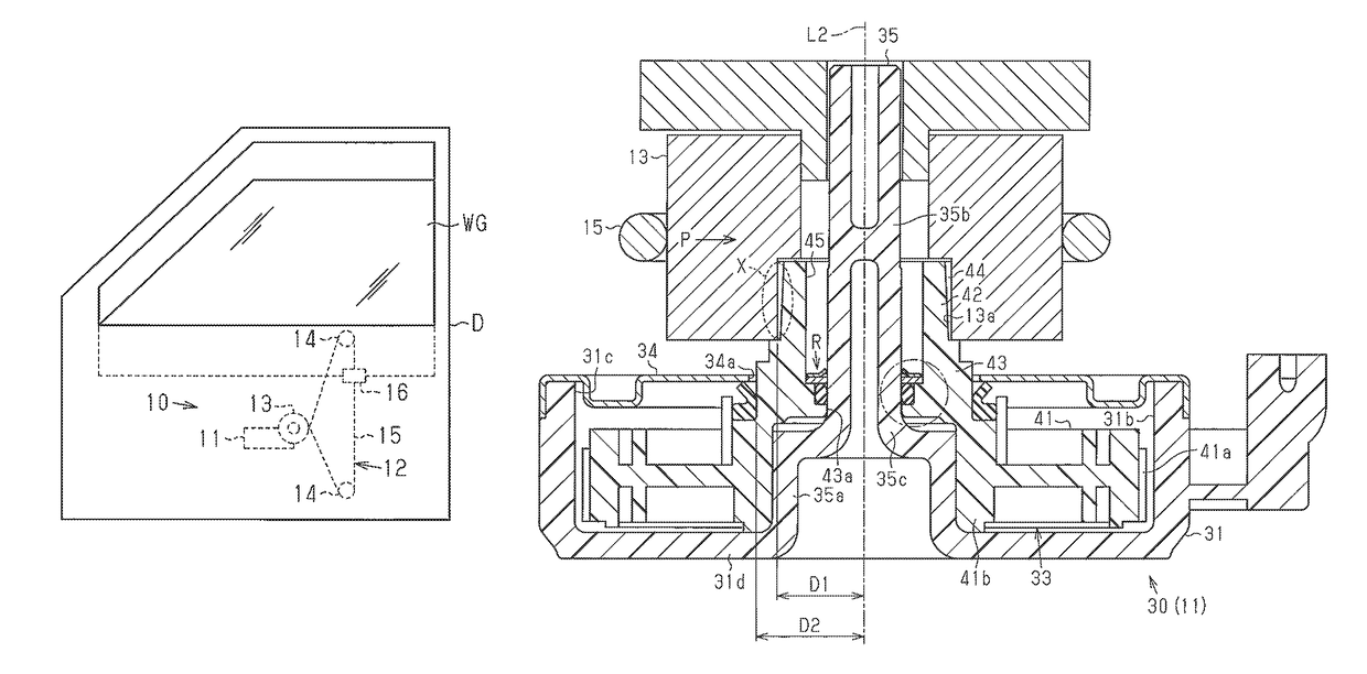
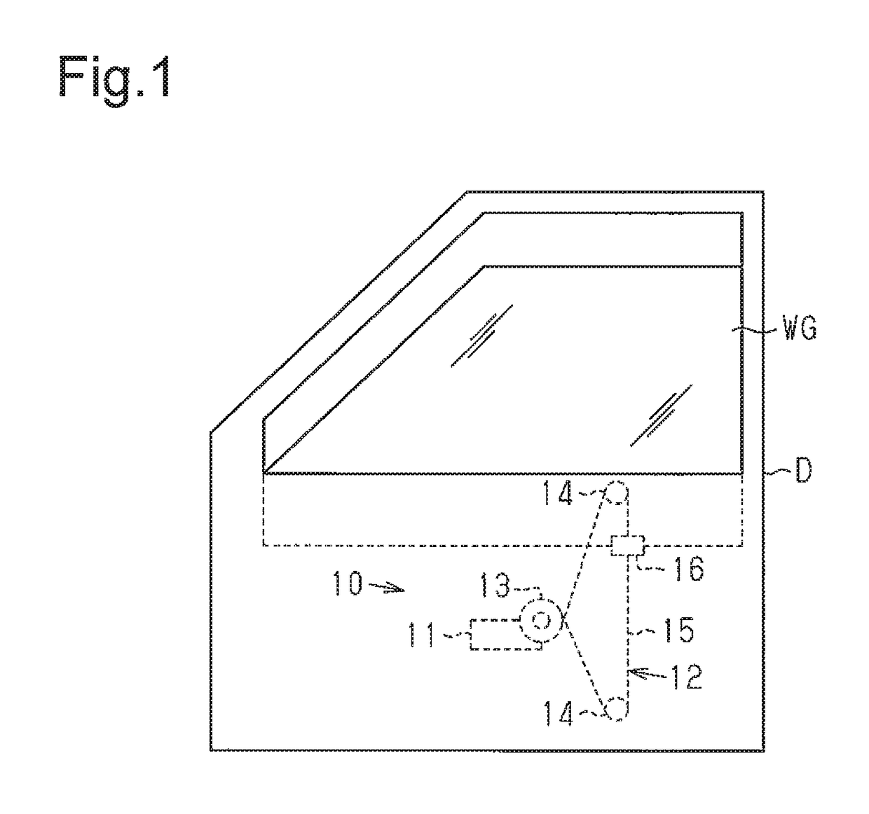
[0014]As shown in FIG. 1, a power window device 10 of the present embodiment is coupled to a vehicle door D to open and close a window glass (window body) of the vehicle door D. The power window device 10 includes a geared motor 11 and a wire-type window regulator 12. The geared motor 11 is coupled to the vehicle door D. The window regulator 12 opens and closes the window glass WG when driven by the rotation produced by the geared motor 11.

[0015]The window regulator 12 includes a drive pulley 13, which is coupled to the geared motor 11, two driven pulleys 14, and a wire 15, which runs around the drive pulley 13 and the two driven pulleys 14. The drive pulley 13 functions as an input member, to which the output of the geared motor 11 is transmitted. A portion of the wire 15 that is located between the two driven pulleys 14 is held by a fixed member 16, which is fixed to the window glass WG. When th...


PUM


Abstract

A geared motor includes a motor and a reduction drive. The reduction drive includes a gear housing, a speed reduction-output member, and a restriction portion. The gear housing includes a support shaft. The speed reduction-output member includes a reduction gear, an output gear meshed with an input member, and an accommodation recess. The speed reduction-output member is rotationally supported by the support shaft. The restriction portion is configured to restrict movement of the speed reduction-output member relative to the support shaft. The restriction portion is located between an outer circumferential surface of the support shaft and an inner circumferential surface of the accommodation recess. The restriction portion is located in an axial direction of the support shaft at a position that differs from a portion where the speed reduction-output member abuts in a radial direction against the input member.

Description

BACKGROUND OF THE INVENTION[0001]The present invention relates to a geared motor and a power window device that includes a geared motor as a drive source.[0002]Japanese Laid-Open Patent Publication No. 2013-108549 discloses an example of a geared motor including a motor and a reduction drive, which are integrally coupled to each other. A gear housing of the reduction drive includes a support shaft, a speed reduction-output member is rotationally supported by the support shaft. The speed reduction-output member includes a reduction gear (worm wheel in the above publication) that reduces a rotation speed of the motor and an output gear that is rotatable integrally with the reduction gear. The support shaft is fitted into the speed reduction-output member and inserted through the reduction gear and the output gear. The output gear of the speed reduction-output member is meshed with an input member, which is located outside the geared motor. Thus, the rotation produced by the motor is r...

Claims


Application Information

Patent Timeline
Patent Type & Authority Patents(United States)
IPC IPC(8): B60J1/08F16H57/12E05F15/697F16H19/06F16H1/16
CPCE05F15/697B60J1/08F16H19/06F16H57/12E05Y2201/434E05Y2900/55F16H1/16F16B21/18F16H57/021F16H57/039F16H2057/0213H02K7/116
Inventor KOIZUMI, TAKUYA
Owner DENSO CORP
Why Eureka
Try Eureka