Film conveying mechanism and extrude-emptying mechanism of automatic vertical type filling and packaging machine

A technology of conveying mechanism and packaging machine, applied in the field of food packaging, can solve the problems of unfavorable sealing and welding function of sealing and welding device, bearing damage, shaft deformation, etc., and achieve the effect of ensuring sealing and welding function, reducing deformation and enhancing stability.

Pending Publication Date: 2018-09-07
BEIJING AEROSPACE ORIENTAL TECH DEVCO
View PDF7 Cites 0 Cited by
  • Summary
  • Abstract
  • Description
  • Claims
  • Application Information

AI Technical Summary

Problems solved by technology

The larger the cantilever length, the greater the radial stress on the guide wheel shaft 306, which is likely to cause deformation of the shaft and damage to the bearing.
[0004] At the same time, the cantilever-type squeezing roller and conveying wheel will generate greater vibration during operation. The longer the cantilever length is, the greater the shaft end runout will be, and the excessive vibration will be transmitted to the seal set above the conveying and squeezing device welding device, so that the sealing welding function of the sealing welding device is extremely adversely affected

Method used


Image

  • Film conveying mechanism and extrude-emptying mechanism of automatic vertical type filling and packaging machine
  • Film conveying mechanism and extrude-emptying mechanism of automatic vertical type filling and packaging machine
  • Film conveying mechanism and extrude-emptying mechanism of automatic vertical type filling and packaging machine

Examples


Embodiment Construction

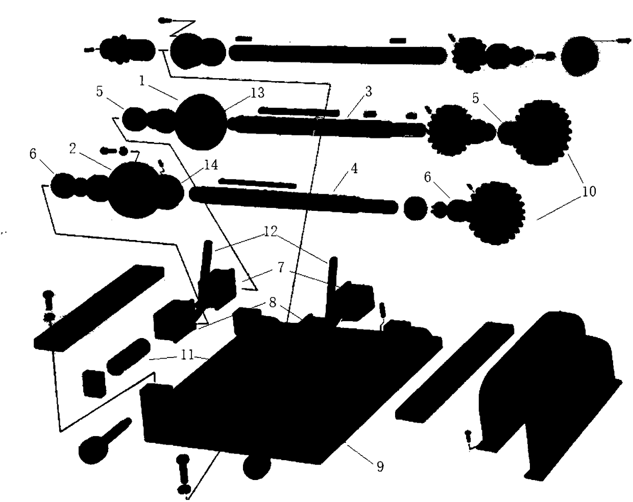
[0068] figure 1 It is an exploded schematic view showing a film conveying mechanism of an automatic vertical filling and packaging machine according to various embodiments of the present invention.

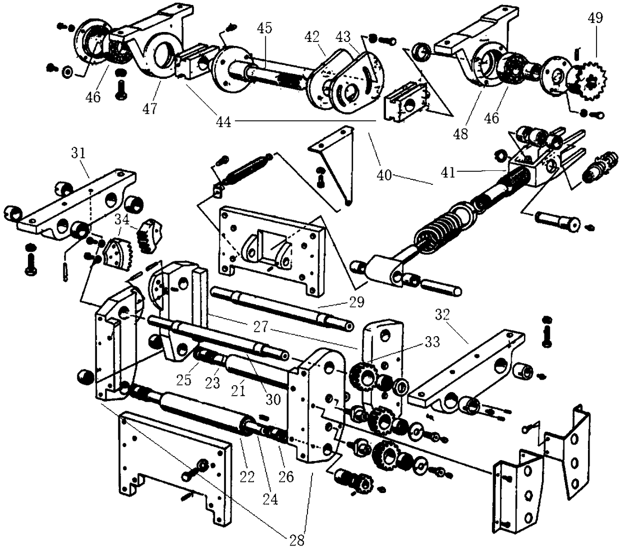
[0069] figure 2 is a perspective view illustrating a film conveying mechanism of an automatic vertical filling and packaging machine according to various embodiments of the present invention.

[0070] Such as figure 1 with figure 2 As shown in, the film conveying mechanism of the automatic vertical filling and packaging machine according to the present invention includes a pair of conveying wheels 1, 2, a stationary conveying wheel shaft 3, a movable conveying wheel shaft 4, a stationary bearing seat 7, a movable bearing seat 8, a support 9 and Leverage12.

[0071] A pair of conveying wheels 1 and 2 are respectively installed in the middle of the stationary conveying axle 3 and the movable conveying axle 4 through flange bushings 13 and 14, and the flange bushings 13 and 1...


PUM


Abstract

The invention relates to a film conveying mechanism and an extrude-emptying mechanism of an automatic vertical type filling and packaging machine. The two ends of conveying wheel axles of the film conveying mechanism are connected with static bearing pedestals and movable bearing pedestals, the static bearing pedestals are fixedly installed on a support, the movable bearing pedestals are movably installed on the support, the support is fixedly connected with an intermediate plate, and a conveying and pushing mechanism is arranged between the static bearing pedestals and the movable bearing pedestals and can control the movable bearing pedestals to be close to or far away from the static bearing pedestals. Extrude-emptying rolls of the extrude-emptying mechanism are installed in the middlesof extrude-emptying roll shafts, the two ends of the extrude-emptying roll shafts are connected with extrude-emptying brackets, the upper ends of the extrude-emptying brackets are fixed to rotating shafts, the two ends of the rotating shafts are connected with fixing brackets on the two sides, the fixing brackets are fixedly connected with the intermediate plate, the back-side extrude-emptying bracket is provided with an extrude-emptying pushing mechanism which can push the back-side extrude-emptying bracket to do reciprocating motion around the corresponding rotating shaft, and the extrude-emptying rolls are close to each other and far away from each other through fan-shaped gears which are arranged on the rotating shafts and mesh with each other.

Description

technical field [0001] The invention relates to the technical field of food packaging, in particular to a film conveying and emptying mechanism of an automatic vertical filling and packaging machine. Background technique [0002] At present, the film conveying mechanism of the automatic vertical filling and packaging machine mostly adopts a cantilever type single support method, that is, the conveying wheel is installed on one end of the rotating shaft for axial rotation, and the other end of the rotating shaft is supported on the bearing bracket through a bearing. The squeeze mechanism also adopts such a cantilever single support method. Such a method will generate a large radial stress on the rotating shaft, which will easily cause deformation of the shaft and damage to the bearing. [0003] Chinese utility model patent ZL200920106622.7 discloses a cantilever traction device and a three-column automatic filling and ligating machine. Image 6 It is a schematic diagram of t...

Claims


Application Information

Patent Timeline
Patent Type & Authority Applications(China)
IPC IPC(8): B65B41/16B65B65/02B65H79/00
CPCB65B41/16B65B65/02B65H79/00
Inventor 郑长青李盼盼
Owner BEIJING AEROSPACE ORIENTAL TECH DEVCO
Why Eureka
Try Eureka