flywheel
a technology of radial stress and flywheel, which is applied in the field of flywheel, can solve the problems of significant internal distortion of the flywheel, high stress generated inside the flywheel, and likely over-the-weight of the flywheel, and achieve the effect of reducing radial stress and increasing speed
- Summary
- Abstract
- Description
- Claims
- Application Information
AI Technical Summary
Benefits of technology
Problems solved by technology
Method used
Image
Examples
first embodiment
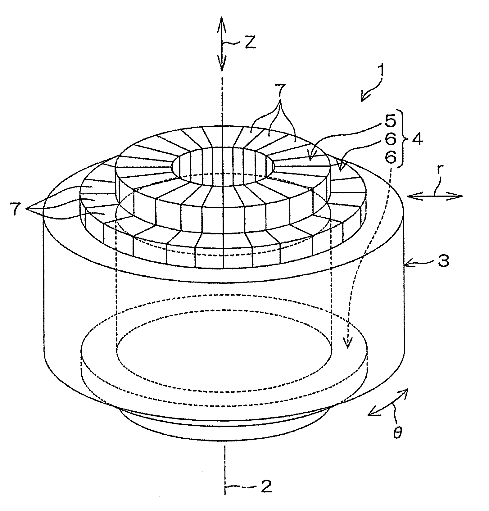
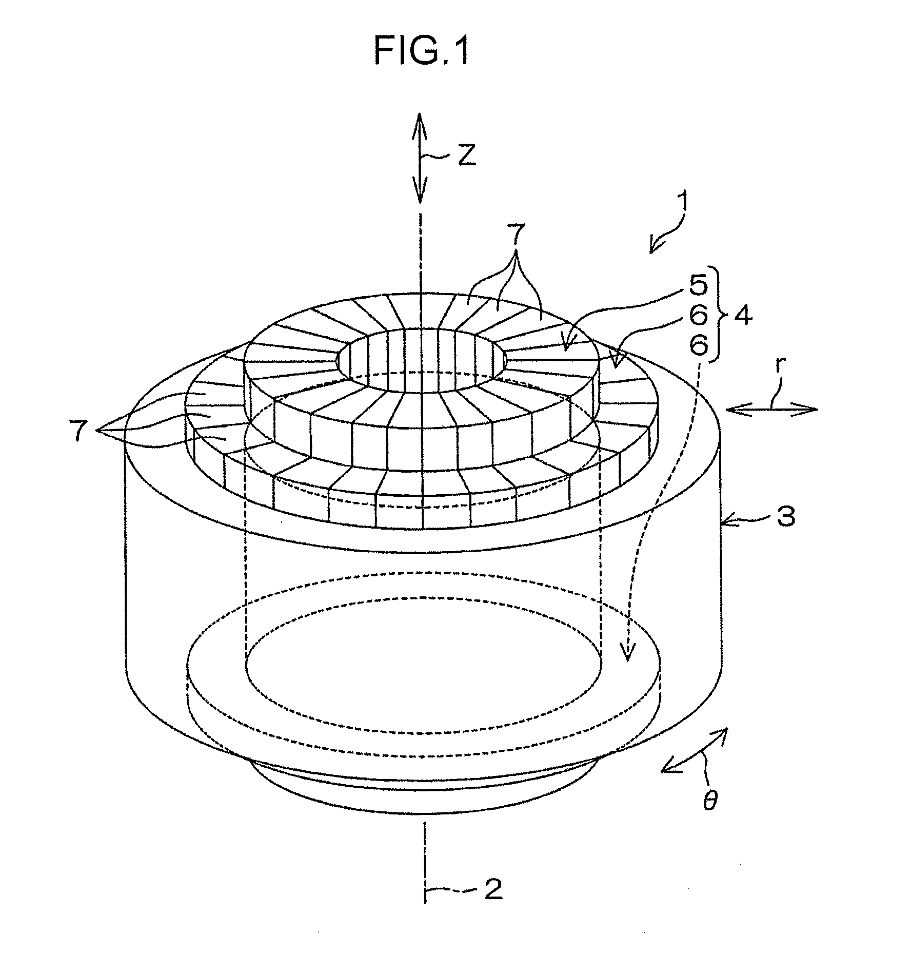
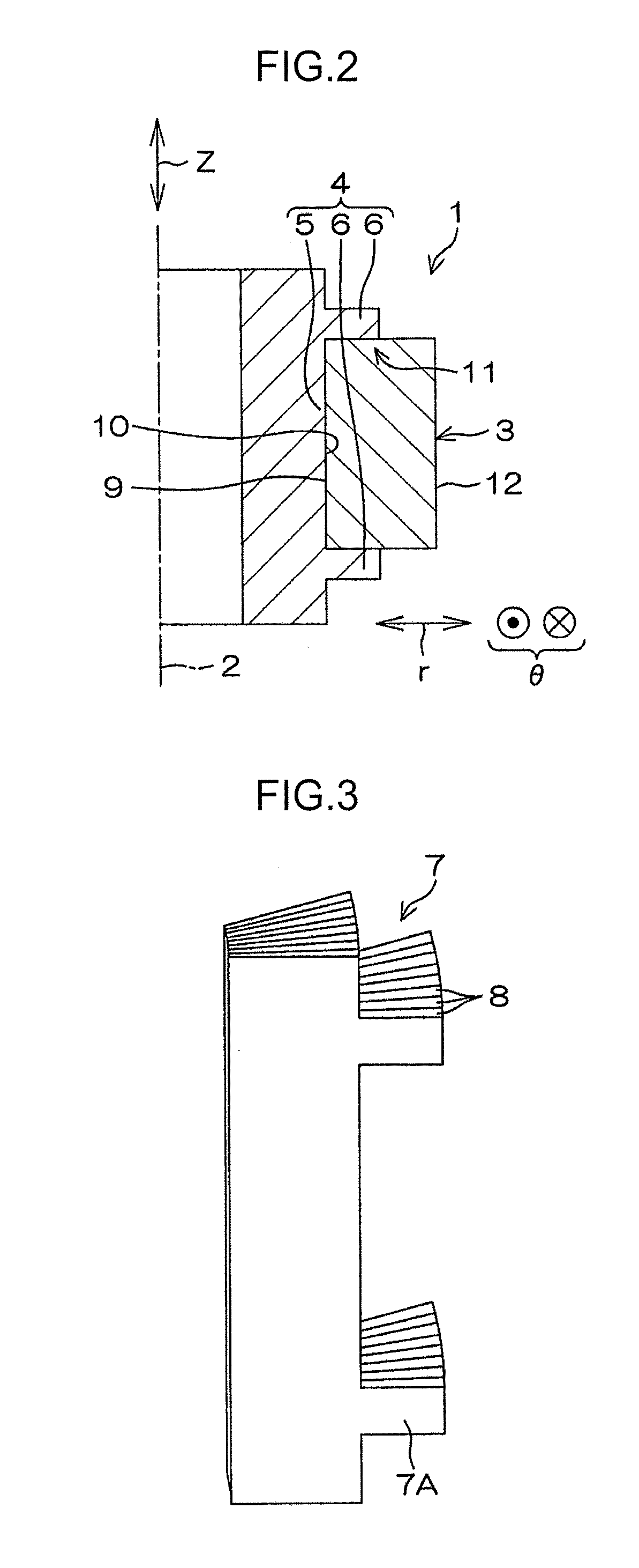
[0022]Embodiments of the present invention will be described below with reference to the attached drawings. FIG. 1 is a perspective view depicting a configuration of a flywheel 1 according to the present invention. FIG. 2 is a sectional view of the flywheel 1. FIG. 3 is a perspective view depicting a configuration of a divided element 7 included in the flywheel 1. FIG. 4 is a diagram depicting a configuration of a carbon fiber prepreg 8 included in the divided element 7.
[0023]The flywheel 1 is hollow and generally cylindrical, and is mounted in a flywheel battery apparatus (not depicted in the drawings). In the flywheel battery apparatus, the flywheel 1 is provided so as to be rotatable, in a horizontal orientation, around a vertical axis of rotation 2, for example. Components such as a rotating shaft (not depicted in the drawings) extending along the axis of rotation 2 and electrical components are housed in a hollow portion of the flywheel 1. Since the components are housed in the...
second embodiment
[0036]Since the direction in which the carbon fibers in the wheel ring 3 are oriented is the circumferential direction θ, the wheel ring 3 has a high rigidity and a high strength in the circumferential direction θ. Therefore, even when the rigidity of the hub ring 4 included in the flywheel 1 is set low in the circumferential direction θ, the flywheel 1 as a whole can still have a high rigidity and a high strength in the circumferential direction θ. FIG. 5 is a perspective view depicting a configuration of a divided element 27 included in a hub ring 24 according to the present invention.
[0037]The hub ring 4 is divided into a plurality of equal pieces (for example, 24 equal pieces). In other words, the hub ring 24 is divided into the pieces in the circumferential direction θ by division surfaces 27A perpendicular to the circumferential direction θ. As a result, the hub ring 24 includes the plurality of (for example, 24) divided elements 27. The divided element 27 according to the sec...
fifth embodiment
[0048]Example: A measurement target was the flywheel 51 according to the The inner diameter dimension of the hub ring main body 5 was set to 220 (mm), the outer diameter dimension of the flange 56 was set to 260 (mm), and the thickness of the flange 56 in the axial direction z was set to 10 (mm). The inner diameter dimension of the wheel ring 3 was set to 240 (mm), the outer diameter dimension of the wheel ring 3 was set to 500 (mm), and the dimension of the wheel ring 3 in the axial direction z was set to 200 (mm).
[0049]Comparative example: A measurement target was a flywheel formed of CFRP and configured as an integral member. The inner diameter dimension of the flywheel was set to 240 (mm), the outer diameter dimension of the flywheel was set to 450 (mm), and the dimension of the flywheel in the axial direction z was set to 200 (mm). Under these conditions, the in-plane distribution of the stress in the radial direction r in the vicinity of a central position in the wheel ring (...
PUM
 Abstract
Description
Claims
Application Information
 - R&D
- Intellectual Property
- Life Sciences
- Materials
- Tech Scout
- Unparalleled Data Quality
- Higher Quality Content
- 60% Fewer Hallucinations
Browse by: Latest US Patents, China's latest patents, Technical Efficacy Thesaurus, Application Domain, Technology Topic, Popular Technical Reports.
© 2025 PatSnap. All rights reserved.Legal|Privacy policy|Modern Slavery Act Transparency Statement|Sitemap|About US| Contact US: help@patsnap.com


