
Extrusion deformation fastener and assembling method thereof

A technology of extrusion deformation and fasteners, applied in the direction of threaded fasteners, locking fasteners, connecting components, etc., can solve problems such as failure to meet assembly requirements, failure of product assembly, slipping of wrench tools, etc., to achieve Simple structure, easy to process and manufacture, avoid slipping effect

Inactive Publication Date: 2021-11-05
烟台中天连接技术研究院
View PDF7 Cites 0 Cited by
  • Summary
  • Abstract
  • Description
  • Claims
  • Application Information

AI Technical Summary

Problems solved by technology

[0005] However, in actual use, when fasteners and nuts are assembled, because of the large designed torque value, especially when products with smaller specifications are assembled with each other, the assembly torque may exceed the limit torque of the hexagonal groove in the bolt, resulting in During the installation process, the inner hexagonal groove "slips" and damages the inner hexagonal groove, which cannot meet the assembly requirements
And in order for the hexagonal wrench tool to be inserted into the hexagonal groove, there must be a certain fit gap between the two, and the fit gap will easily make it difficult for the wrench tool and the hexagonal groove to meet face-to-face and have a large area of ​​contact. Therefore, the wrench When the torque is applied to the screw tool, the torque is often concentrated in the local contact area of ​​the hexagonal groove structure, resulting in high local stress. The high stress causes the hexagonal groove to deform, forming a slope, and the wrench tool "slips", resulting in product assembly failure

Method used


Image

  • Extrusion deformation fastener and assembling method thereof
  • Extrusion deformation fastener and assembling method thereof
  • Extrusion deformation fastener and assembling method thereof

Examples


Embodiment Construction

[0027] In order to enable those skilled in the art to better understand the solutions of the present invention, the technical solutions in the embodiments of the present invention will be clearly and completely described below in conjunction with the drawings in the embodiments of the present invention.

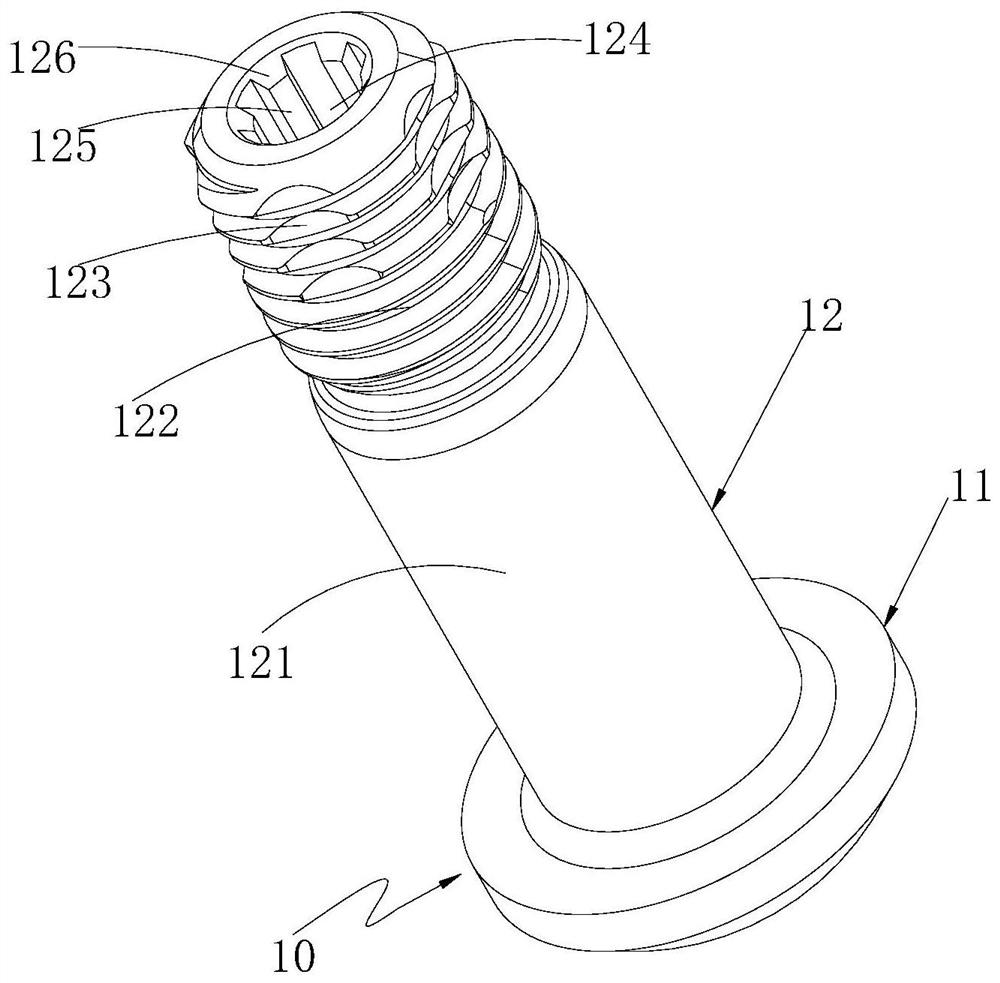
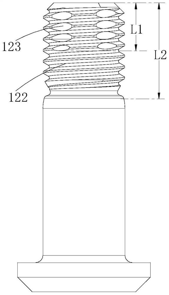
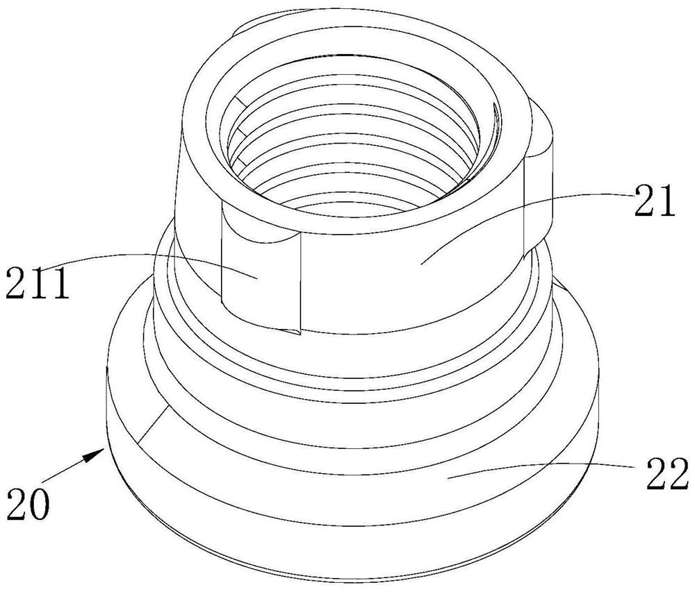
[0028] refer to figure 1 , figure 2 , Figure 6 and Figure 7 , an extrusion deformation fastener, the fastener 10 includes a head 11 and a rod body 12, the rod body 12 has a smooth section 121 and a threaded section 122, the head 11, the smooth section 121 and the threaded section The section 122 is set as an integral structure, and the head 11, the smooth section 121 and the threaded section 122 adopt known structures and designs; the outer wall of the threaded section 122 is provided with at least one recess 123, and the high lock nut 20 is deformed by extrusion The rear part squeezes into the recesses 123 to form self-locking; preferably, five recesses 123 are arrange...


PUM


Abstract

The invention discloses an extrusion deformation fastener and an assembling method thereof. The extrusion deformation fastener comprises a head part and a rod body, and the rod body is provided with a smooth surface section and a threaded section; the outer wall of the threaded section is provided with a concave part into which a part of a high-lock nut is extruded after being extruded and deformed so as to form self-locking; and a wrenching groove is formed in the end face of the side, away from the head part, of the threaded section in the axis direction of the rod body, and a plurality of tooth parts are arranged on the inner wall of the wrenching groove at intervals. The concave part is arranged on the outer wall of the threaded section, the high-locking nut is extruded into the concave part to form self-locking with the high-locking nut after being extruded and deformed by external force, so that the extrusion deformation fastener is simple structure and easy to process and manufacture, has the characteristics of rapidness in assembly and reliability in connection, and has high practicability and easiness in vigorous popularization.

Description

technical field [0001] The invention belongs to the technical field of high-lock fasteners, and in particular relates to an extruded deformation fastener and an assembly method thereof. Background technique [0002] High-lock fasteners (such as high-lock bolts) and high-lock nuts are mainly used in aircraft structures, such as the connection of aircraft splints, aircraft cabins, skins, etc., and have self-locking properties. Fasteners generally consist of a bolt head, a screw with a threaded section starting at the tail of the screw, [0003] When in use, usually the mounting holes are drilled at the connection part first, then the fasteners are passed through the connection holes, and the high lock nuts are screwed into the fasteners until they contact the connection plate to form a pre-tightening force, and finally the loading can make the The high torque of the lock nut will break the wrenching part and complete the installation. The existing high-lock nuts and fastener...

Claims


Application Information

Patent Timeline
Patent Type & Authority Applications(China)
IPC IPC(8): F16B39/28F16B39/282F16B23/00
CPCF16B39/28F16B39/282F16B23/0038
Inventor 黄鑫李迪
Owner 烟台中天连接技术研究院
Learn More